

Creating a Cylinder
Cylinders are commonly used features after boxes. In AutoCAD, you can create cylinders easily by using the Cylinder tool. You can create a circular or elliptical cylinder by using this tool.
Click Home > View > View Style drop-down > Wireframe on the ribbon; the view style of the model will be changed wireframe.

Also, change the model view from SE Isometric to NE Isometric from In-canvas Controls.

Deactivate the 3D Object Snap on the status bar and ensure that the Object Snap in turned on.

Click Home > Modeling > Primitives drop-down > Cylinder on the ribbon or type CYL in the command line.
Specify the center point of the cylinder on the inclined face of the wedge. You can use thetracelines from the midpoints of the vertical and horizontal edges of the face.
Type the base radius as 18 and press ENTER.

Move the cursor upward; you will notice that the cursor moves along the Z-axis of the UCS.
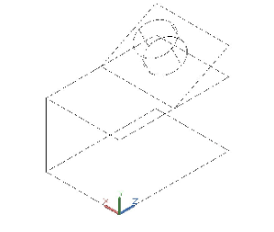
Type 24 as height and press ENTER; the cylinder will be created as shown below.

Example : (Returning to previous position of the UCS)
Click Home > Coordinates > UCS, Previous on the ribbon; the UCS will return to its previous position.

If you change the model view from NE Isometric to SE Isometric from In-canvas Controls, the object looks.

Example : (Creating a UCS by specifying its origin)
Click Home > Coordinates > Origin on the ribbon; the UCS will be attached to the cursor.
Select the lower left corner point of the box; the UCS will be placed at that point. Note that the orientation will not change.

Example: (Rotating the UCS about X, Y, and Z axes)
You can rotate a UCS about X, Y, or Z axes by using the drop-down available in the Coordinates
panel, as shown below.

Click the X option from the drop-down
shown in the above figure; the message,
“Specify rotation angle about X axis
<90>:” appears in the command line.
Also, a rubber band line originating from
the Y axis is attached to the cursor.
Rotate the cursor and pick a point to
specify the rotation angle. You can also
type-in the rotation angle in the dynamic
input or command line.

Similarly, you can rotate the UCS about
the Y and Z axes using the respective
options from the drop-down.
Example: (Creating the UCS by specifying the Z-axis)
Using the Z-Axis Vector tool, you can create a UCS by specifying its Z-axis.
Click Home > Coordinates > Z-Axis Vector on the ribbon.
Select the bottom right endpoint as the origin; the message, “Specify point on positive portion of Z- axis:” appears in the command line. Also, a rubber band line originating from the Z-axis is attached to the cursor. Now, as you move the cursor, you will notice that the Z-axis also moves.
Move the cursor and select the right endpoint of the bottom right edge as shown below; the Z- axis will be aligned to the bottom edge.

Example: (Creating UCS parallel to the screen)
Using the View tool in the Coordinates panel, you can create a UCS which is parallel to the screen.
Click Home > Coordinates > View drop-down > View on the ribbon;
the XY plane of the UCS will become parallel to the screen. The UCS origin will not change. This option is useful if you want to use the current view and add a title block, or any other annotation.

Example: (Creating UCS aligned to an object)
You can create a UCS aligned to an object. The origin of the UCS will be aligned to the nearest endpoint of the object.
Click Home > Coordinates > View drop-down > Object on the ribbon; the message, “Select object to align UCS:” appears in the command line.
Select the cylindrical object from the model; the UCS will be aligned to it.

Example: (Creating
UCS
aligned
to
face)
You can align a UCS to a planar or curved face of a model using the Face tool.
Click Home > Coordinates > View drop-down > Face on the ribbon; the message, “Select face of solid, surface, or mesh:” appears in the command line.
Move the cursor over the front faces of the model; you will notice that the UCS is
displayed on the faces.

Now, click on the selected face of the box; the message, “Enter an option [ Next Xflip Yflip ] <accept>:” appears in the command line. If you select the Next option, the adjacent face will be highlighted. The Xflip option is used to rotate the UCS 180 degrees about the X axis. The Yflip option is used to rotate the UCS 180 degrees about the Y axis.
Press ENTER to accept; the UCS will be aligned to the selected face.


