
Concrete Frame and Shear Wall Design
Auto Loading Combinations and Design Groups
For concrete frame and shear wall design, ETABS creates load combinations based upon
the design code chosen and different load cases defined. To select a specific code for
concrete design, go to Options>Preferences>Concrete Frame Design. For this example,
choose the ACI 318-05/IBC 2003 design code. There are many design parameters that
can be defined such as different PHI values, number of interaction curves and utilization
factor limit. We will use all of the default values. Refer to Figure 22.
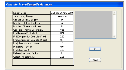
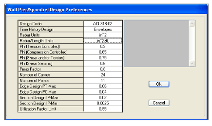
Figure 22 Concrete Frame Design Preferences
The same can be done for concrete shear wall design. To select a specific code for shear
wall design, go to Options>Preferences>Shear Wall Design. For this example, choose the
ACI 318-02 design code. Again, there are different design parameters that can be defined.
As was the case for concrete frame design, we will use all of the default values. See
Figure 23:
Figure 23 Shear Wall Design Preferences
Go to Design>Concrete frame Design> Select Design Combos. All of the available
design load combinations are listed in the List of Combos list box. The design load
combinations actually used in the design are listed in the Design Combos list box. Use the
buttons on the form to move the load combinations into and out of the Design Combos
list box to specify which combinations will be used during the design process. For our
model, we have a very high number of design load combinations (78). This is due to the
face that we defined 12 different wind load cases, an earthquake load case, as well as the
default DEAD and LIVE cases.
Select a load combination and click Show to see how a specific load combination has
been defined. The default concrete frame design load combinations have names like
DCON1, DCON2 and so on. Refer to Figure 24.
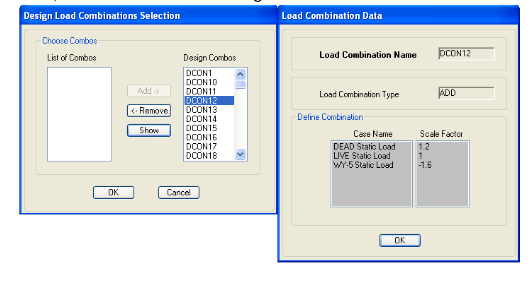
Figure 24 Design Load Combination
The load combination scale factors will be affected if you go to Define>Special Seismic
Load Effects and select Include Special Seismic Data Design. When this option is
selected, the program calculated (or user defined) Rho factor and the user defined DL
Multiplier are automatically applied to program default design load combinations for
American codes (ACI, AISC, UBC) that include contributions from earthquake loads.
Earthquake loads in this case are assumed to be all static loads of type QUAKE, all
response spectrum, and all time history cases. These factors must be applied manually by
the user for other design load combinations. ETABS calculates the Rho factor in
accordance with Section 1617 of the 2000 International Building Code. The automatic
calculation of the Rho factor depends on the floor area. ETABS calculates the floor area
at each story level by summing the areas of the floor-type area objects at each story level.
Important Note: The calculation of the Rho factor also depends on the ratio of the
design story shear resisted by the most heavily loaded element in a story divided by the
total story shear. This ratio is designated rmax. The value of rmax can only be calculated if
there is lateral load in the model. The Rho factor can only be calculated if rmax is nonzero.
Thus, the Rho factor is only calculated when there is lateral load present in the model.
The calculated Rho factor along with intermediate results are output as part of the
database displayed Building Output.


