
Modeling of Pier and Spandrel Elements
Draw a wall on gridline G between gridlines 6 and 8. To do this, make sure you are in the
plan view of Story 12 and the All Stories option is enabled in the bottom right hand corner
of the screen. Go to Draw>Draw Area Objects>Draw Walls (plan). Click on grid
intersections G8 and then G6.
The next step in this model is to mesh the elevator core wall to create door openings.
There is a new drawing option in ETABS that allows the user to directly draw doors in an
elevation view. First, we will need to create reference lines along the front of the elevator
core (gridline 8). Reference lines are vertical lines at user-specified global X and Y
coordinates. The reference lines are useful for snapping when drawing objects in elevation
or plan view. Right click the mouse and select the Create Reference Lines on
Plan option. Enter 2.5 feet in the Plan Offset X box. Click on the intersections of
Gridlines 8E and 8F. Reference lines appear as points in plan view. Repeat this step
using –2.5 ft in the Plan Offset X box and click on the Grid intersections 8F and 8E
We need to assign reference planes to define top of the elevator doors. Reference Planes
are horizontal planes at user-specified Z-ordinates. The main purpose of those planes is to
provide a horizontal plane/line that you can snap to when drawing objects in elevation
views. You can also view reference planes in a plan view. This option can be useful for
adding mezzanine-type framing when you have not specified the mezzanine as a story
level in the story data. In this case, the reference planes will signify the top elevation of
the openings to be created in our shear walls. Go to Edit-> Edit Reference Planes-> and
enter elevations of 8ft, 20ft, 32ft, 44ft, 56ft, 68ft, 80ft, 92ft, 104ft, 116ft, and 128ft and
click OK.
Use the Draw>Draw Areas>Draw Doors to create a door at the 1st level in between the
assigned reference lines. Use the snap to lines and edges option to help create the door.
You may need to use the reshape tool to make the door the correct size. When in reshape
mode, click on an area object and a series of selection handles (squares that are the
opposite color from the background color) will display at all corners of the area object,
indicating that the program is in reshape mode and that the area object has been selected.
Then move the area object by dragging or reshape it by dragging or specifying
coordinates, as follows
Once the door is drawn, select the door and go to Edit>Replicate>Story tab and select
floors 2-12 and click ok. Use the replicate command to create doors on the other side of
the elevator core. See Figure 14.
We want to mesh the walls so we can assign pier and spandrel labels to them. Select the
entire wall on elevation 8 and go to Edit>Mesh shells and click on the
Mesh/Quads/Triangles at Intersections with visible grid lines. You can delete the
reference planes after you finish meshing the walls. Please refer to Figure 14:
Lastly, we need to replicate this entire elevator door mesh to elevation 2. (Be sure to first
delete the existing elevator core shear walls at elevation 2). Select everything shown on
elevation 8. Go to Edit>Replicate> Linear Tab. Enter –91ft in the dy box and click OK.
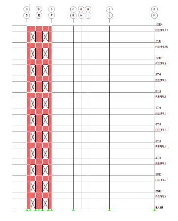
Figure 14 Elevator Core Mesh
A wall pier or spandrel can be made up from a combination of both area objects (shell
elements) and line objects (frame elements). To get output forces reported for wall piers
or to design wall piers, you must first define them. Define a wall pier by selecting all of
the line and/or area objects that make up the pier and assigning them the same pier label.
This can be done by going to Assign->Shell/Area->Pier Label or Spandrel Label. Assign
Pier and Spandrel labels for the shear wall on Elevation 8.
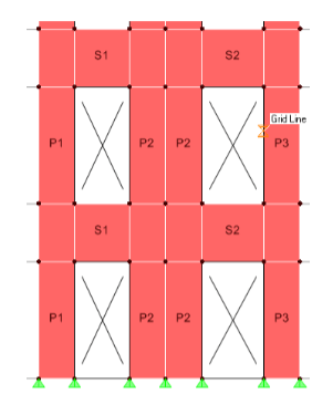
It is important to note that when you assign pier labels, you must select all area objects
that make up the pier and assign them the same pier label. However, when working with
many wall piers on the same story level, use separate pier labels for every wall pier. If
you do not do this, the shear wall design output will combine all wall pier forces with
identical pier labels. See Figure 15.
Figure 15 Pier/Spandrel Labels


