
Model Creation (Floors/Walls, Columns and Beams)
As shown in Figure 1, this structure has 2 rounded terraces on the east and west faces that
run from the 7th to the 12th floor. It would be difficult to accurately locate the points of
these edges. To solve this problem, we will import the terraces and floor elements from a
.D XF file. This command will import the floor elements to the model. Click the File
menu > Import > DXF Floor Plan command to access the DXF Import form. Use the
form to locate the filename/path of the .DXF file to be imported. Select the DXF layer
names (Floors) that contain the area elements and insertion points in the DXF file. Make
sure that you insert the floor at the 12th level. Your plan should look like Figure 8:
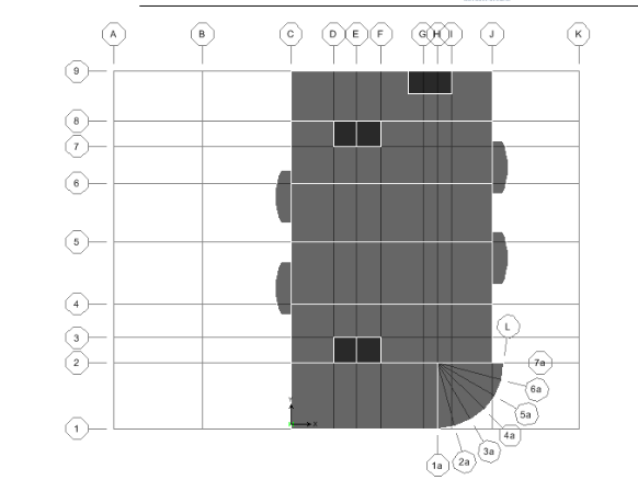
Figure 8 Floor Slab Layout (7th-12th Stories)
The darker floor elements represent the elevator cores and stair openings. Select the 5
area elements and go to Assign > Shell/Area > Opening to create holes in the slab. All
floor elements were brought in as DECK elements. However, we want to use slabs for the
floor elements in this model. To assign a Slab element to the floor, go to
Assign>Wall/Slab/Deck sections. Select the SLAB1 property and click on the
Modify/Show Section button. Select the CONC material type, enter an 8 in. thickness for
both membrane and bending and click OK.
Make sure the ‘Similar Stories’ option is enabled in the bottom right corner of the screen
and select all of the floor elements. Go to Assign>Wall/Slab/Deck Section and select the
SLAB1 property and click OK.
Next, we want to replicate this 12th story down to the 6th story. In plan view, select all of
the floor elements and go to Edit>Replicate>select the Story tab. Highlight the 6th-12th
floors and click OK. You now have the entire slab elements defined at the top portion of
the structure.
Now, we will manually draw the floor elements that occur at floors 6. These underground
floors were not included in the .DXF file. Only the top floors (7-12) containing the
terraces were created in AutoCAD We will use the same SLAB1 property type as we did
for floors 7-13. To draw the floor objects, go to the 6th floor plan view and click the
Draw>Draw Area Objects>Draw Areas. Again, make sure the ‘Similar Stories’ option is
enabled. Follow the floor plan as shown in Figure 9:
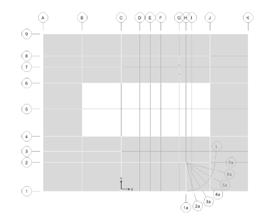
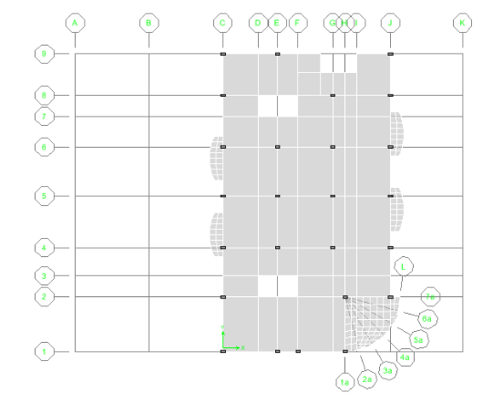
Figure 9 Floor Slab Layout (1st-6th Stories)
It is now time to add the shear walls to the structure. To define wall elements, go to
Define>Wall/Slab Deck section. Select the WALL1 property and click on Modify/Show
Section and enter a 12″thick section. There will be a detailed discussion about the
meshing and defining of 2D and 3D Shear Walls in a later chapter.
Go to the 12th floor plan view and make sure the similar stories option is enabled. Also,
turn on the Snap to Intersection option under the Draw menu. Go to Draw>Draw Area
Objects>Draw Wall. Select the WALL1 property and carefully draw shear walls around
the perimeter of the structure. Be careful to snap to all of the points on the outside of the
terraces. At times, you may find it difficult to snap to the point that you want to. If you
zoom into that area, using the rubber band zoom, the snapping to the desired point will be
easier.
To draw the elevator core walls, just as we did in the last step, go to Draw>Draw Area
Objects>Draw Walls, select the WALL1 property and draw in the perimeters of the
elevator cores just as you did for the walls on the perimeter of the building. To find the
location of where to draw the elevator cores, please refer to figure 9 below.
To draw in the elevator openings, use the Draw>Draw Area Objects>Draw Areas
command, and select the opening property. The elevator cores and stair opening walls
run the entire height of the building .The model should now look like Figure 9:

Figure 9 Wall Layout
The columns are the next elements to be modeled. Go to Define > Frame Section and
from pull down menu, select add Rectangular. Give the column a section name of
CONC24x36 and enter the values shown in Figure 10:
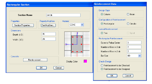
Figure 10 Concrete Column Definition
For cracked section analysis, you can click on the Set Modifiers button and change the
scale factor of the Moment of Inertia. Modifiers can be used on shear walls as well.
Modification factors can be defined as part of frame section properties and assigned
directly to line objects. Note that when modification factors are assigned directly to a line
object that also has modification factors defined as part of its frame section properties,
the two factors are multiplied. Therefore, it is intended that you specify modification
factors using frame section property definition or line object assignment, not both.
The first set of columns run the entire height of the structure. Go to the 12th floor plan
view and select the All Stories option in the bottom right hand corner of the screen.
Activate the Draw menu > Draw Line Objects > Create Columns in Region or at Clicks
(plan) command, and select the CONC24x36 property. There are two ways you can draw
the columns: 1) left click at any location in a plan view to draw a column (vertical line
object below), or 2) while working in plan view, depress and hold down the left button on
your mouse and drag your mouse to rubber band a window around one or more grid line
intersections then release. Columns (vertical line objects below) are automatically placed
at each grid line intersection. NOTE: If you wanted to draw columns that didn’t fall on
grid intersections, this can be done very easily using the Plan Offset X and Plan Offset Y
options that are in the column drawing menu. The columns locations are shown in Figure
11.
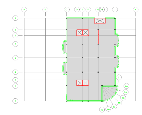
Figure 11 Concrete Column Location (7th – 12th Stories)
There are additional concrete columns that are added at 6th story. These columns
continue down to the 1st story and are used to support the underground parking garage
and ramps. Use the draw commands discussed earlier to create the columns located on
the lower levels. Please refer to Figure 12:
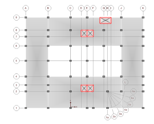
Figure 12 Concrete Column Location (1st – 6thth Stories)


