
Meshing of Concrete Floor Systems and Auto Line Constraints
During analysis, ETABS automatically meshes (divides) area objects that are assigned
deck properties or slab properties with membrane behavior only. For this example, we are
using slab type elements; therefore, we must mesh the slabs manually. First, select all of
the floor elements (from Select>Area Object Type>Floors) and go to
Assign>Shell/Area>Area Object Mesh Options. Click on the Auto Mesh Objects into
Structural Elements button. Then, select the 1st three options. These options are 1) Mesh
at beams and other meshing lines 2) Mesh at wall and ramp edges and finally 3) Mesh at
visible grid lines. Meshing helps distribute loads realistically. In some cases you may not
want ETABS to automatically mesh an area object into the analysis model.
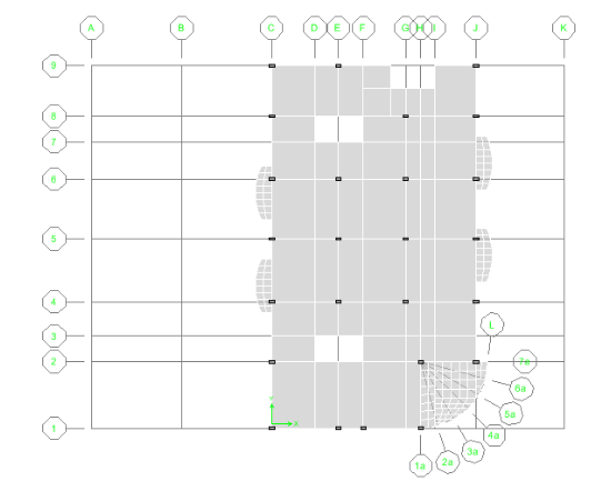
For the curved terraces, the mesh may not be dense enough to ensure proper load transfer,
which may result in some warning messages. To remedy this situation, select the curved
terrace objects and select the 4th option, ‘Further subdivide auto mesh with maximum
element size…’ and enter 42in. As you can see in Figure 13, the mesh is much more
dense at the select locations. To view the meshing, go to View>Set Building View
Options>and click on Auto Area Mesh.
Figure 13 Typical Mesh of Slab
In this model, all mesh points do not connect to the corner points of the terraces. In
typical finite element analysis, shell elements are connected to other elements at corner
points only. When an element does not frame into the corner point of a shell element, but
instead frames into the edge of the shell element, no connection exists between the
element and the shell element. ETABS is able to perform the analysis in this fashion.
However, ETABS also has a very powerful feature called an Auto Line Constraint. The
ETABS auto line constraints feature allows you to specify that elements framing into the
edge of a shell element be connected to the shell element. ETABS internally takes care of
connection between the elements by constraining points lying along an edge of the shell
element to move with that edge of the element. This option is located under the Assign
Menu> Shell/Area> Auto Line Constraint. By default, the Auto Line Constraint feature in
ETABS is active (i.e. turned on). You have to flexibility to use the line constraint on
the entire model or specific elements of the model. Additional information regarding the
auto line constraint functionality in ETABS can be found at the end of this manual in a
paper entitled “Mesh Transitioning and Compatibility using the auto line constraint in
ETABS and SAP2000″.


