
ASCE 7-02 Wind Loads and Auto-permutation of Wind Directions
Next, we will define the wind load cases to the model. Perform the same operation as
discussed earlier to define a wind load case. This time we will apply a wind load in the
Y-direction. Give the load case a name of WY, select a WIND load type and select the
ASCE 7-02 code from the pull down menu. Click the Modify Lateral Load button to
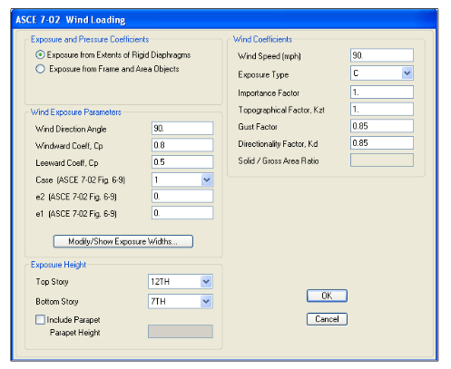
bring up the menu shown in Figure 19:
Figure 19 ASCE 7-02 Wind Load Definition
We have defined rigid diaphragms to this model, so select the ‘Exposure from Extents of
Rigid Diaphragms’ option. The width of the diaphragm is calculated by the ETABS. To
apply the wind load in the Y-direction, enter 90 degrees for the wind direction angle. The
windward and leeward coefficients are defined as 0.8 and 0.5 respectively.
A new feature in ETABS allows the user to define one wind load case and the program
will automatically create all of the remaining wind load cases. The ASCE 7-02 wind code
must be used for this feature to be activated. The e1 and e2 values changes for each
subsequent wind load case based on Figure 6.9 as well as the wind direction angles in the
ASCE 7-02 code. A total of 12 different wind load cases will be defined. Enter all of the
remaining Wind Coefficients shown in Figure 19.


