

Using View Templates, Creating the Miscellaneous Plans and
Details (Roof Framing Plan, Foundation Plan, and Foundation
Details)
In this tutorial part, you will be introduced to the concept of view templates and creating the miscellaneous plans that would be needed for a residential project. You will not be adding any specific information for these plans, these drawings will be a place holder for a structural engineering or designer to add their information. Revit does have specialized tools that may be used to add this type of information. This is included with this program and may be used to help you complete these drawings.
- Open the RL5-5 file. Save the file as RL5-6.
-
Click on the View Templates tool in the View tab, Graphics panel.
- Click on the Manage View Templates option in the drop-down menu.

View Templates Tool, Manage View Templates Option
- The View Templates dialog opens.

View Templates Dialog Box
On the left side in the Names: box there are various templates that you can use on a project. On the right in the View Properties area, there are various view settings that you can change to modify the appearance of the view. You can also change a view and then create a new template.
In these next few steps, you will complete an exercise to illustrate the process of creating a view template.
-
Close the View Template dialog box. Open the Site Plan view.
If the view is shaded, change the visual style to Hidden Line. Turn off the shadows using the Shadows On/Off toggle.
Hide the Reference Planes (if applicable). Your view should look like this…

Shadows On/Off Toggle

Site Plan View
- Right click on the Site Plan view in the Project Browser.
- Select Duplicate View, Duplicate with Detailing.
-
Rename the view, Site Plan – Shaded.
- You now have two views that look the same. Next you will change the appearance of the shaded view.
-
While in the Site Plan – Shaded view, change the visual style to shaded.
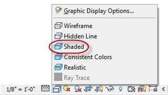
Shaded Visual Style
- Turn on the shadows by clicking on the Shadows On button.
-
Your view should now look like
this…

Shaded View of Site Plan
Creating a New View Template
Next, you will create a View Template from these settings and apply it to the other non-shaded site plan view.
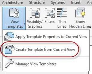
- Click on View Templates, Create Template from Current View.
-
Name the view: Site Plan – Shaded
- The View now appears in the View Templates List.
- Click OK to close the dialog box.
Create Template from Current View Tool
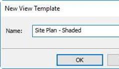
New View Template
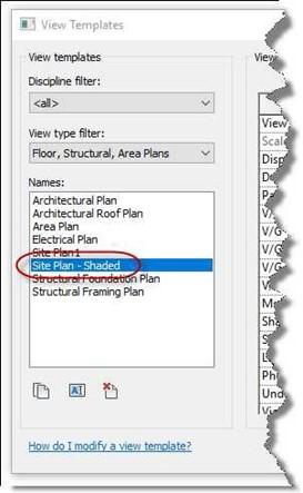
Template Added to List
-
Switch to the Site Plan view (non-shaded).
-
Click on View Templates, Apply Template Properties to Current View.
-

Apply Template Properties to Current View
-
Select the Site Plan – Shaded template.
- Click the Apply Properties button.
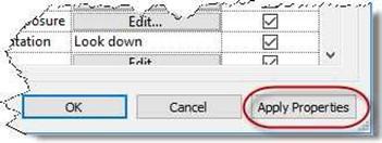
Apply Properties Button
- The view is shaded, and the view properties match the other view.
- Return the view to the previous settings.
Setting up the Roof Framing View
The purpose of a Roof Framing plan is to show the structure of the framing for the roof. Rafter size and spacing, plywood thickness, and other information.
-
In the Project Browser find the Roof Framing view. This view is provided with the template file.
Rename the view ROOF FRAMING PLAN.
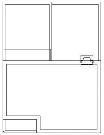
- Click on the view to open it. Hide the reference planes and the generic model of the elliptical arched opening.
You will see that most of the view is grayed out except for the chimney. The walls beneath the roof are not visible.
- If the roof at the south end of the structure is not showing, adjust the View Depth to -7-0″.

View Depth Setting
- To show the walls, set the Underlay to Second Floor.
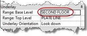
Underlay Set to Second Floor
- This view would be the view that you would add the Roof Framing elements and notations.
Information on this plan would include:
- Ridge Beam size
- Rafter size and spacing
- Roof Material
- Header size for second floor headers
- Other general information.

Roof Framing Plan with Second Floor Underlay Turned On
- This will be the plan that you will include in the Portfolio.
Setting up the Foundation Plan View
The Foundation Plan view is used to show the structural support of the foundation of the structure. Slab thickness, reinforcement location and size, footer size and location, and other information is shown.
- Open the First Floor view.
-
Duplicate the view without detailing and rename it FOUNDATION PLAN.
- Click on the View Templates tool and click Apply Template Properties to Current View.
- Select the Structural Foundation Plan name and click the Apply Properties button.
- Click the OK button to close the dialog box.
-
To set up the appearance of this view do the following:
- Select all the floor elements and hide the surface patterning using the Override Graphics in View option.
- Since the main floor slab has split faces, hide the floor slab.
- Hide the Stairs.
- Hide the Room Separator lines.
- Hide the Furnace and Water Heater.
Foundation View Setup
- The Foundation Plan view is now set up. This will be the view that will be in the Portfolio.
Setting Up the Foundation and Framing Details
- Open the GARAGE WALL SECTION view that you created in Part 5.
-
Click on the Callout Tool.
- Select Detail View, Detail as the type.

Detail View Type
-
Add the detail view callout as shown.
-
Double-click on the bubble to open the Detail View.
Move the view to the Detail View category in the project browser.
Note: All of the detail views will be set to a scale of 1″=1′-0″

Detail View Callout Placed

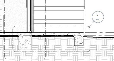
Detail View of Footer
- Rename the view, EXTERIOR BEARING FOOTER.
- Create three additional foundation details. Refer to the following examples.
.
- Open the Longitudinal Section.
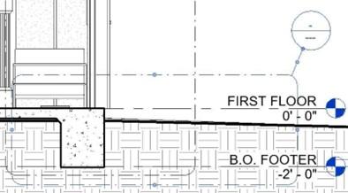
Create a callout view where the garage and floor slab intersect. Include the raised portion in the garage.
Name the detail: GARAGE FLOOR SLAB CONNECTION.
- Create the next detail at the location where the rear porch connects to the main floor slab.
Name the detail: REAR PORCH SLAB CONNECTION.
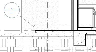
Garage Floor Slab Connection Detail
- Open the Transverse Section view.
Create a callout view where the front porch will be located.
Allow approximately 4′-0″ to
the right of the slab footer.
Name the detail: FRONT PORCH SLAB CONNECTION.
Note: These four details will be placed on the sheet with the Foundation Plan.
Rear Porch Slab Connection
Front Porch Slab Connection
- Also, create four framing details.
Refer to the wall sections for locations.
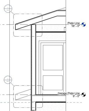
Framing Detail Callouts on Transverse Section Callout #1
Framing Detail Callouts on Transverse Section View
Note: These detail views will be placed on the Foundation and Framing Plan sheets when assembling the Portfolio in Tutorial 7.
- Name the detail at the top of wall section ROOF/WALL CONNECTION.
Name the detail at the second floor and wall SECOND FLOOR/WALL CONNECTION
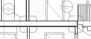
Name the detail on the left side of the transverse section view WALL/FLOOR CONNECTION
Name the other detail at the stairs STAIR/FLOOR CONNECTION
Note: These four details will be placed on the sheet with the Roof Framing Plan.
- Due to the amount of details, create two detail categories.
One is for the framing details and the other is for the foundation details.

.
Detail Categories in Project Browser
-
Open the Transverse section.
- In order to eliminate confusion and to add clarity to the drawing, you will add two additional callout bubbles that reference existing details.
Click on the View, Callout tool.
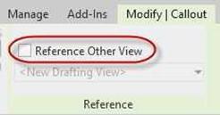
- Look for the Reference Other View checkbox in the contextual tab.
Check the box.
Reference Other View Checkbox
Note: This is used as a way for the designer to provide a link to a detail from
more than one location on the drawing.
- For the first callout at the top left of the Transverse Section view, choose the Detail View: ROOF/WALL CONNECTION in the drop down menu.
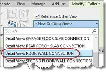
Detail View: ROOF/WALL CONNECTIION
- You will see that the letter Sim (for similar) are placed next to the callout bubble.
Double click on the bubble and it will open the appropriate detail.
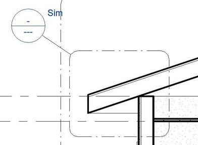
Sim Callout for Duplicated Detail Reference
- Repeat the process for the second callout.
This time, choose the SECOND FLOOR/WALL CONNECTION detail.
- This is the end of Part 6. Save your file as RL5-6.


