
Creating the Longitudinal and Transverse Section Views,
Creating the Wall Sections
In this tutorial you will create Longitudinal and Transverse section views as well as a Wall Section view. You will use these views to create detail views in Part 6 of this book.
- Open the RL5-4 file. Save the file as RL5-5.
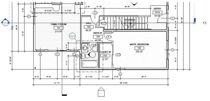
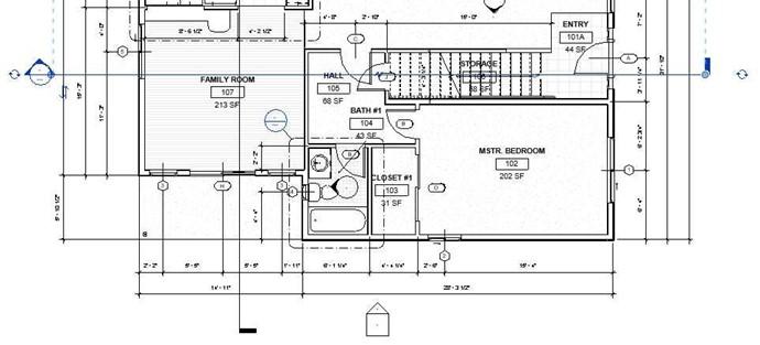
- Open the First Floor view.
- Hide the furniture and the floor lamps that were created in the previous tutorial.
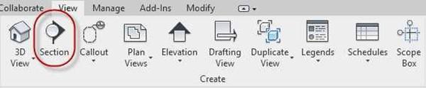 Click on the Section Tool in the View tab, Create panel. This procedure was also given in the RL5-2 tutorial.
Section View Tool
- Starting at the top of the view, click and drag down through the floor plan as shown.
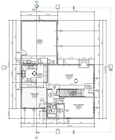
 Section Line Placement
-
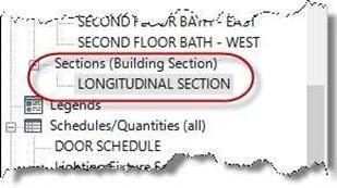
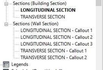
After the line is placed, you will see a new Project Browser view category called:
Sections (Building Section).
Your section view will be named, Section 1.
Rename the view,
LONGITUDINAL SECTION. New View Category
- Repeat the process for the transverse section view. Name the view, TRANSVERSE SECTION.
Transverse Section View Location
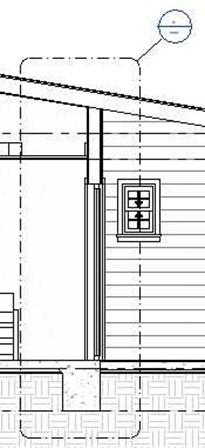
- Open the Longitudinal Section view. Set the view scale to 3/8″=1′-0″.
The view will now look like this…
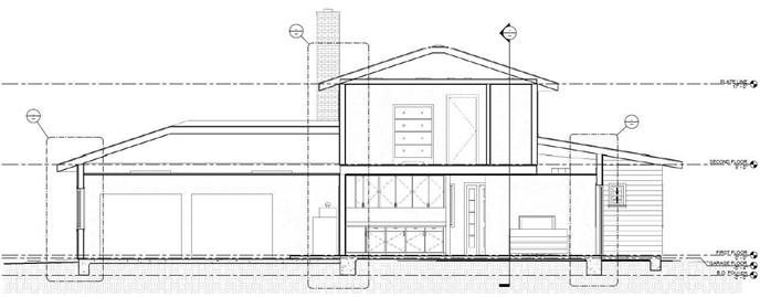
Longitudinal Section View
-
Turn off the tree and people components in the view. Also hide the reference plane elements.
If the Dresser in the second floor bedroom is not showing the drawers, return to the second floor furniture plan view and rotate the dresser 180 degrees.
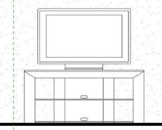
You may need to move the TV – Flat Screen up to the top of the stand. Temporarily turn off the sofa and the coffee table to do this.
TV Moved
- Open the Transverse Section view. Set the scale to 3/8″=1′-0″.
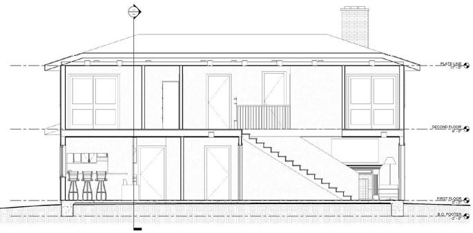
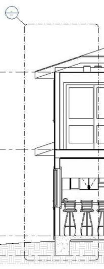
Transverse Section View
Note: If some of the level markers are not appearing in the new section views, open one of the elevation views or other section view. Then, right-click on the level marker that is not visible in the other view and select “Maximize 3D Extents”. This should cause the level marker to appear. If this doesn’t work, check each elevation view and position all level markers (hidden or visible) on the right side of each view.
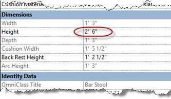
- You will need to adjust the seat height of the bar stools in the Family Room on the left side of the view.
Click on one of the barstools, click the Edit Type… button and change the seat height from 3′-0″ to 2′-6″.
All three barstools will update.
Seat Height Changed
Creating the Level for the First Floor Ceilings
At this point in the project you will create the First Floor Ceiling Level.
This level will be used to indicate the height of the ceiling but will not have a corresponding plan view.
- Open the Longitudinal Section view.
- You will place the First Floor Clg. level.
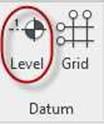
Click on the Level tool in the Architecture tab, Datum panel.
Level Tool
- In the Options Bar, uncheck the Make Plan View checkbox.

Make Plan View Checkbox
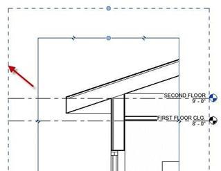
- Start the level line on the left side of the view. Then drag to the right side of the view. When dragging to the right, line up with the existing levels.
-
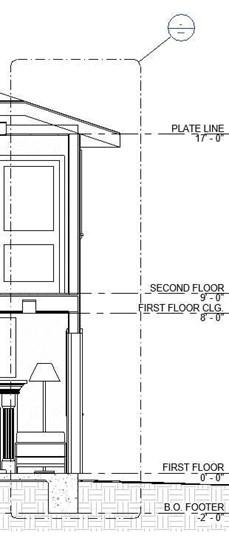
Name the level FIRST FLOOR CLG. and set the
height of the level to 8′-0″.
You will not need a level marker for the Second Floor ceiling since the height is the same as the Plate Line.
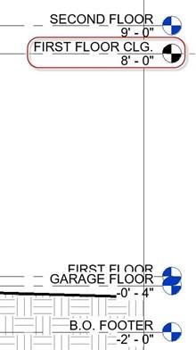
Level Added
Creating the Wall Sections
- Beginning in the Transverse Section view, click on the Callout tool in the View tab, Create panel.
- Select the appropriate type in the Properties box.
You will choose the Wall Section type.
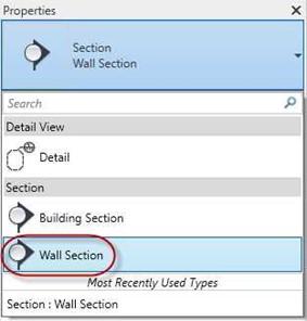
Wall Section Type
- Draw a rectangular boundary around the ends of the house as shown.
Click on the boundary and drag the callout bubbles to the corner of the boundaries.
Callout #1 Callout #2
- Repeat the process in the Longitudinal Section.
Callout #3 Callout #4 Callout #5
- Once the callouts are created, check the Project Browser and make sure that they are in the Sections (Wall Section) category.
If they are not, select the callout in the project browser and change the type selector from Section Building Section to Section Wall Section.
This will move it to the correct category.
Eventually all five Callouts will be placed on a single sheet. Next you will annotate one of the Wall Sections.
Wall Sections in Correct Category
- Open the Wall Section known as Callout #3 in the diagram.
This will appear as LONGITUDINAL SECTION – Callout 1 in the project browser.
You may also double click on the bubble for the callout to open the view.
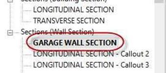
Rename View
Rename the Wall Section: GARAGE WALL SECTION.
- If needed, set the view scale to 3/4″ = 1′-0″. Set the Detail Level to Fine.
- Click on the edge of the Crop Window.
Note the dashed box around the edge, this is the Annotation Crop Window.
Annotation Crop Window
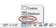
Detail Level Set to Fine
- For your notes to show up, you will need to stretch the annotation crop window away from the view.
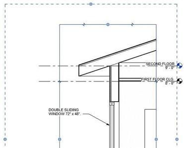
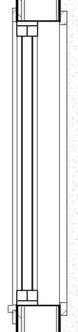
Annotation Crop Window Stretched
- Click on the Second Floor level marker.
Click the check box on the left end to turn on the text and target symbol. Turn off the text and target on the right side.
- Go to the Copy tool and copy the second floor level marker.
Drag the copy up approximately 1′-0″.
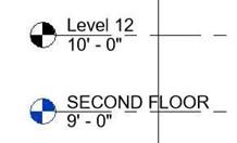
Second Floor Marker Copied
- Hide the second floor level marker.
- Rename the new level marker, GARAGE PLATE LINE. Set the height of the new level to 9′-0″.
- Repeat the process for the FIRST FLOOR CLG. the new level will be GARAGE CLG.
- Add the slope symbol.
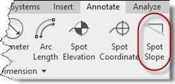
Go to the Spot Slope tool in the Annotate tab, Dimension panel.
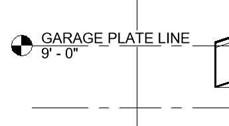
Garage Plate Line Marker Placed
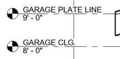
Garage Clg. Marker Placed
Spot Slope Tool
- Set the Slope Representation to Triangle and Offset from Reference to 1/2″.
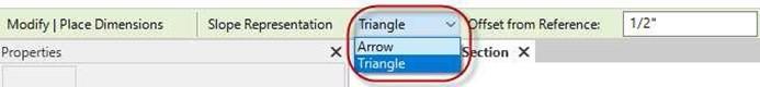
Symbol Settings Changed
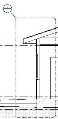
- Click on the roof surface at the top.
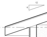 The symbol will appear under the roof surface. Click above the roof surface to place the symbol.
Symbol Placed
- Click on the Component tool in the Annotate tab, Detail panel.
- Add the detail components for the:
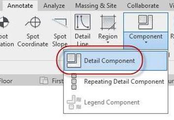
 Detail Component Tool
- 2-2×6 (Double Top Plate)
- 4×6 (Window Header)
- 2×6 (Bottom of Window Opening)
- 2×6 (Sill Plate)
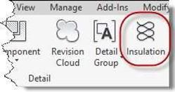
Anchor Bolt 0.5″ Diameter (Anchor Bolt) Insulation Tool
-
Wall Insulation
(Use the Insulation tool in the Annotate, Detail panel. Set to 5 1/2″ Width)
- Break Line
- When placing the Break Lines, you need to adjust the size of the break with the arrows.
Space the break line components approximately 3′- 6″ from each other.
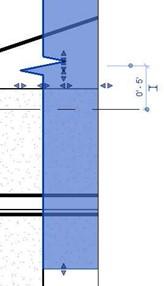 Break Line Adjustment Arrows
- To place the rebar ends, you will use the Region tool in the Annotate tab, Detail panel.
Set the shape to circle in the Draw panel and the Radius to 1/2″.
Select the Filled region Solid Black for the fill pattern.
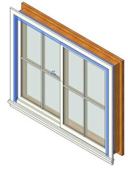
Changing the Visibility of the Trim and Frame of the Window
The trim and the frame for the windows is not visible. In these next few steps you will modify the Double Sliding Window family to make the trim appear.
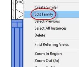
- Right click on the window and select Edit Family.
Note:
If you prefer, a completed version of the Window-Sliding-Double family is available in the custom families in the Windows folder. The name of the file is Window- Sliding-Double (Trim Visible).rfa.
Change the file name to Window-Sliding- Double.rfa prior to loading the family into your drawing.
- The Window-Sliding-Double family opens.
In the Project Browser, expand the Generic Models section.
Right click on the Trim-Window-Exterior- Flat family and select Edit.
Edit Family
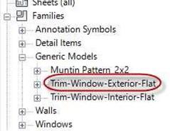 This is a sub-family that is part of the
Window family. Generic Models Tree Expanded
- When the Trim-Window-Exterior-Flat family opens, click on the ViewCube to rotate the object to show the top, front, and right sides.
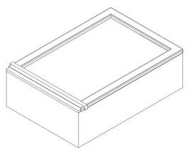
View Rotated
- Select all the elements at the top of the extrusion. There will be four elements.
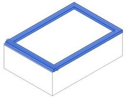
Elements Selected
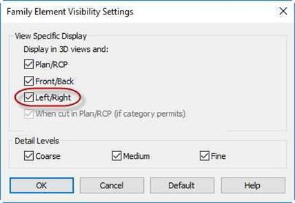
- Click on the Visibility Settings in the Mode Panel.
- In the Family Element Visibility Settings dialog box, check the checkbox next to Left/Right.
This will make the elements visible in the side view.
.
Family Element Visibility Settings Dialog Box
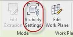
Visibility Settings Tool
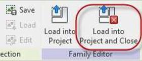
- Click the Load into Project and Close tool in the Family Editor panel.
.
Load into Project and Close Tool
- The Load into Projects dialog box opens.
Select the Window-Sliding-Double.rfa file. This will load the family into the Window family file.
You do not need to save the changes. Select Overwrite the existing version.
.
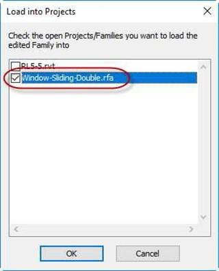
Load into Projects Dialog Box
- Repeat steps 3-8 for the Trim-Window-Interior-Flat family
- In the Window-Sliding-Double family file, select the Frame/Mullion : Sweep element.
Change the visibility to make the element visible in the Left/Right view.
Frame/Mullion : Sweep Element Selected
- Load the Window family back into the project.
Choose to overwrite the family as well as the shared sub-component.
 Trim and Frame Visible.
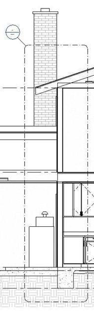
- Continue with the annotation of the Garage Wall section.
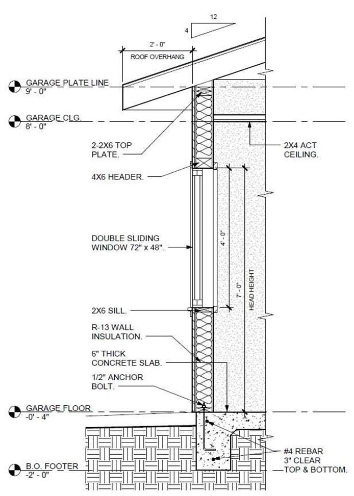
Completed Wall Section
-
Hide the FIRST FLOOR level marker and switch the text for the
B.O. FOOTER and GARAGE FLOOR levels.
-
Use the Text, Two Segments tool to add the dimensions and notes.
Refer to the example for text and placement.
-
When placing the rebar note use the Add Left Side Straight Leader Tool to add an additional segment to the note.
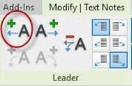
Add Left Side Straight Leader Tool
- Turn off the crop window by toggling the Hide Crop Region toggle in the view control bar.
- This is the end of Part 5. Save your file as RL5-5.


