
Setting up the Isometric and Perspective Section Camera Views
In this last part of the Tutorial you will modify the ceiling in the garage to show ceiling joists as you did for the second floor ceiling. After that, you will set up two isometric section views and one perspective section view of the house.
- Open the RL6-4 file. Save the file as RL6-5.
- Open the Longitudinal Section view. As you did with the second floor ceiling, delete the Garage Ceiling level.
- Open the First Floor ceiling plan view. Zoom in on the garage area.
-
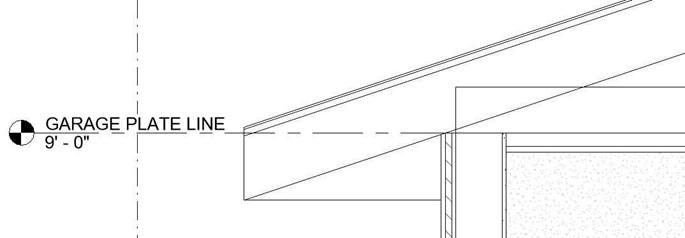
Click on the Ceiling tool. Set the level to Garage Plate Line and the offset from level
to 0′-0″. Place the edge of the ceiling on the outside edge of the wall core.
-
- Open the Longitudinal Section view.
Since you have created design options you will need to switch to the 1-Hip Roof option. Detach the top of the north garage wall from the bottom of the roof.
New Ceiling Placed and Ceiling Raised
- Open the default 3D view of the house.
This view is a non- perspective view.
Shade the view if it
isn’t already shaded.
Default 3D View
- Duplicate the view and name it: Longitudinal Section.
This view will cut through the garage and rest of the house.
- Go to the Properties box and scroll down to the Extents area.
Click on the checkbox for the Section Box.
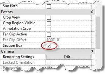
Section Box Checkbox
- A box will appear around the 3D view.
Click on the edge and drag the side using the blue arrows.
Section Box Arrows
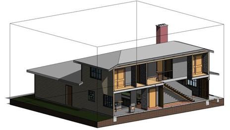
- Drag the arrows until your view looks like this…
Turn on the shadows in this view and the next section view. Name the view: Longitudinal Section.
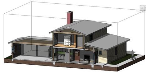
Longitudinal Section
- Duplicate the view and set up to look like this…
Name the view: Transverse Section.
Transverse Section
- For the all the section views, set the background color to white.
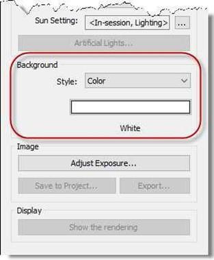
Background Color Set to White
- Place both views into the To Be Rendered view category and create rendered views of them.
Creating the Perspective Section View
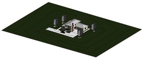
- Create a new camera view from the Site Plan.
Name the view Perspective Section.
Note:
You may also create a non- perspective section view as you did in the previous section and then convert it to a perspective view by changing the Projection Mode in the view properties.
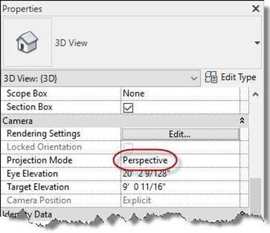
Projection Mode Set to Perspective
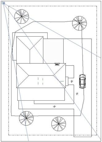
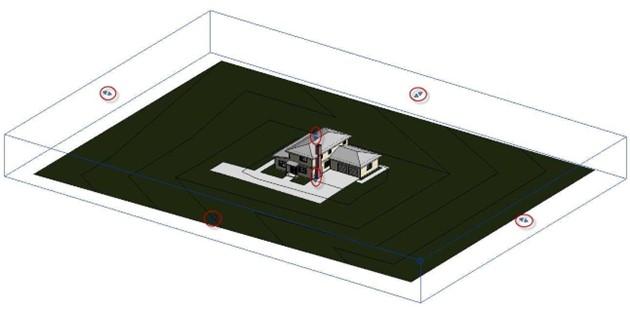
Camera Location for Perspective Section View
- Once the view opens, go to the Properties for the view and check the section box checkbox.
Hide the trees, people, and car.
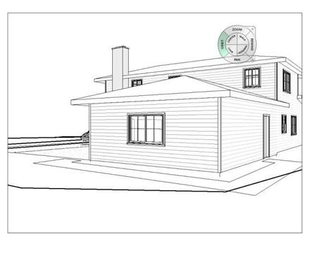
- Click on the Steering Wheel icon on the right and drag it out into the drawing.
You will need to use this tool to zoom, pan, and orbit the view.
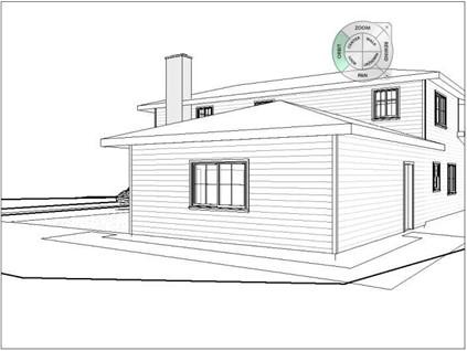
Perspective View with Section Box and Steering Wheel Tool
- Click the Section Box checkbox in the Properties box.
- Using the Zoom option on the wheel, zoom out so that you can see the section box.
- Close the Steering Wheel and click on the edge of the section box.
- Adjust the view and the edge of the crop window until the section is located at the desired location.
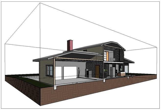
Completed Perspective Section
- The view is now ready to be rendered. You do not need to hide the section box.
- This is the end of Part 5 and Tutorial Six. Save your file as RL6-5.


