

Setting Up the Design Options, Exterior & Interior
3D Views, and Renderings
Starting the Tutorial
-
Start Revit 2021 by clicking on the icon on the desktop.
-
Open the last file from Tutorial Five, RL5-6.
-
Save the file as RL6-1.
In this tutorial you will set up two different design options of the project. One will show two different roof styles and the other will show two different porch options. After that you will setup the exterior and interior camera views for the project.
Once those views are set up you will either render the views using the Revit
software or Autodesk’s Cloud Rendering service.
Creating the Front Porch Design Options
In this part of the tutorial you will create two design options for the front porch of your house. There is currently no covering or porch and the front door into the house, so you will start by creating what will be known as the Primary Option.
Before beginning this procedure, you will need to paint the fascia board surfaces.
- Open the Default 3D view.
- Zoom in on the house.
- Go to the Materials tool in the Manage tab, Settings panel.
- Search for Paint in the search area.
-
Duplicate the Paints and Coatings material and name it Paint – White.
- In the Appearance tab, click on the Duplicates this asset button.

Duplicates this asset. Button
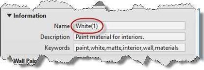
- This will create a new asset called White(1).
Note: Once a material asset is created, it cannot be deleted, only renamed.
New Asset Created
- You may change the material or leave it white.
If you wish to use a different color, change the name of the material and the asset.
-
Close the Material Browser.
- Click on Paint tool in the Modify tab, Modify panel. Select the Paint – White material.
- Click on the edge of all the fascia surfaces to paint them with the new material. Close the material browser when finished.
Creating the Porch Area
- Open the Site Plan view.
-
Set the cut plane of the view to 4′-0″.
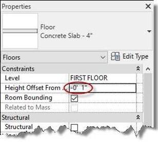
- Start with the Concrete Slab – 4″ type.
Set the level to FIRST FLOOR with a height offset of -0′ 1″.
Porch Floor Settings
- To find the center of the opening, temporarily turn on the Door category and add a reference plane at the center of the door.
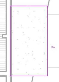
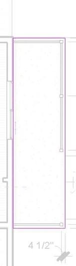
Draw the boundary as shown and center it on the front door.
vv
Align the left edge of the porch slab with the core of the wall face.
Click the Green Check to complete the floor.

Front Porch Sketch Boundary
- Next, add a footer around the bottom edge of the slab.
Open the 3D view and rotate to see under the slab.
-
Hide the topography so that you can see the bottom corners of the slab.
- Click on the Slab Edge tool and add the Porch/Garage Footer slab type to the outside three edges of the slab.

Footers Added to Porch Slab
- Rehide the topography and open the Site Plan view.
- Set the cut plane of the view to 10′-0″.
Next you will add the porch roof.
- Click on the Roof tool.
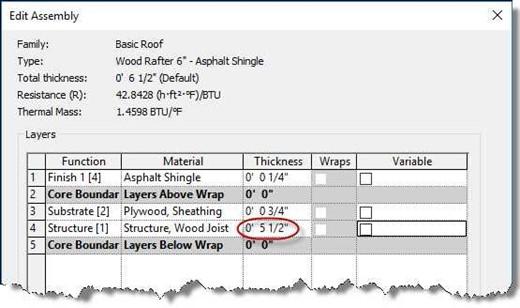
- Starting with the Basic Roof Wood Rafter 8″ – Asphalt Shingle roof style, create a new style called: Basic Roof Wood Rafter 6″ – Asphalt Shingle.
The only change will be to change Layer 4 (Rafter Height) from 7 1/4″ to 5 1/2″.
Roof Settings
 Draw the boundary of the roof as shown.
The edge of the roof will match the edge of the porch slab.
The right-side edge will be sloped. Use these settings for the roof:
- Base Level – FIRST FLOOR
- Base Offset From Level – 8′-0″
- Rafter Cut – Two Cut – Plumb
- Slope – 3″ / 12″
-
Switch to the 3D view.
Porch Roof Sketch Boundary
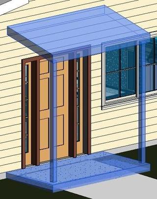
- Your porch will look like this…

Porch Roof and Slab
- Paint the fascia with the same Paint – White material as before.
- Open the Site Plan view.
-
Change the cut plane to 4′-0″.
- Click on the Column tool, Column: Architecture in the Architecture tab, Build panel.
Select the Wood Timber Column 4 x 4 family.
Add the two 4×4 posts 4 1/2″ from each corner of the porch slab.
You may use dimensions or reference planes to locate the posts.
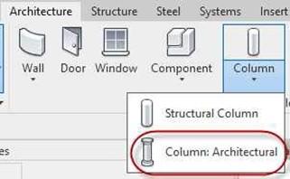
Column: Architectural Tool
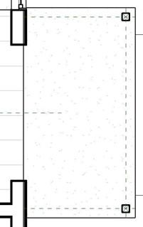
4 x 4 Posts Added
-
Open the 3D view.
- After adding the Posts, attach the top of the posts to the roof using the Attach Top/Base tool.
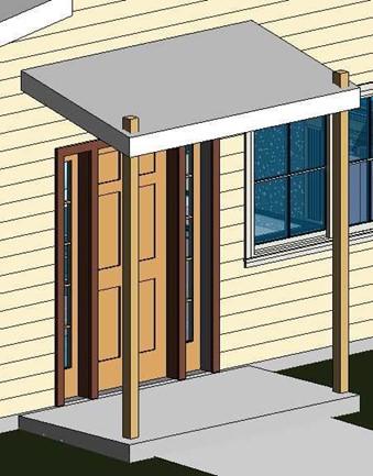
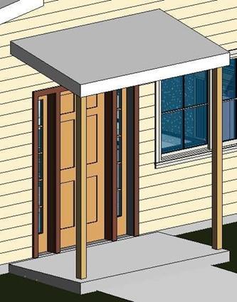
Before Attaching the Posts to the Roof After Attaching the Posts to the Roof
- Click on the posts and set the Base Offset to -0′-1″.
Setting Up the Design Options
At this point, you will begin the process of creating the two design options. Although not required, you will use the existing elements to create the second option.
- While still in the 3D view, open the Design Options dialog box.

Design Options Tool
-
The Design Options dialog box opens.
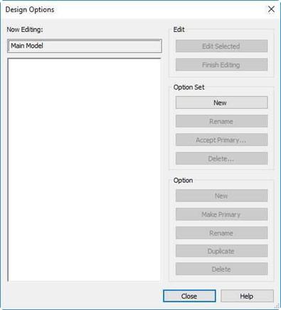
Design Options Dialog Box
- Click on the New button under the Option Set.
Create two option sets, “Front Porch” and “Roof”.
- With the Front Porch option set selected, click the New button under the Option area.
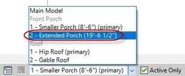
Create two options, 1 – Smaller Porch (8′-6″) and 2 – Extended Porch (19′-6 1/2″).
- Select the Roof option, click the New button under the Option area. Create two options, 1 – Hip Roof and 2 – Gable.
- When finished your Design Options dialog box should look like this…
Click Close to close the dialog box.

Design Options Dialog Box with Options Added
- Next you will add the front porch elements to the two Front Porch Design Options.
Select the porch slab, the two 4 x 4 posts, and the porch roof.
Note: The porch footers will be selected with the porch slab.
Porch Elements Selected
- Click the Add to Set tool at the bottom of the screen next to the Design Options
 tool. Add to Set Tool
- The Add to Design Option Set dialog box opens.
Select the Front Porch option if necessary.
Click the OK to close the box and add the elements to the two options.
Note:
What just happened is the four elements that were selected were removed from the main model.
Then two sets of the four elements were added back into the model, one for each of the Design options.
This way you will be able to change the second set of elements without affecting the first set.
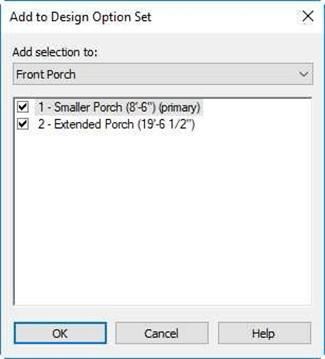
Add to Design Option Set Dialog Box
You may notice that now you are not able to select any of the four elements. To access these elements, you will need to activate one of the design options for the front porch.
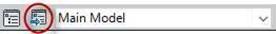
 Click on the Active Design Option drop-down at the bottom of the screen.
Select the first option on the Front Porch option.
Active Design Option Drop-Down
- The rest of the model will gray out and you will be able to pick the four elements.

Front Porch Option #1 Elements
- Now you will be able to change these elements to create the elements for Front Porch Option #2.
Open the Site Plan view.
- Click on the Active Design drop-down and choose Front Porch Option #2.
Option #2 Chosen
-
For the Front Porch Option #2 you will make the following changes.
- The dimensions of the porch slab with change to 5′-6″ x 19′-6 1/2″. The footers will move with the edge of the slab.
- Two additional posts will be added. The four posts will be placed in the following locations. You will need to switch back to the Main Model to hide/delete the reference planes for the original posts. When moving the two original posts you will receive an error message. Accept the error and then move the posts.
-
Three handrails will be added between the 4×4 posts.
They will need to be added one at a time using the Railing tool. Use the Railing Handrail – Rectangular type.
-
The roof footprint will be changed to match the edge of the enlarged porch slab. Keep the slope of the roof at 3″/12″.
(Change the cut plane to 10′-0″ before modifying the roof.)

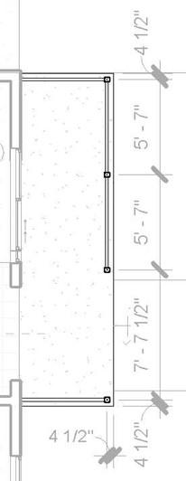 Option #2 Porch Slab
Dimensions 4×4 Post Locations
-
Open the 3D view.
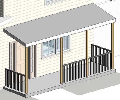
Enlarged Roof Footprint
- Before completing the tutorial, you will modify the stair railing. Click on the railing and then the Edit Type button.
-
The Type Properties dialog box opens for the Railing family.
Click the Duplicate… button and name the family type Handrail – Rectangular (2 Rails)
Click on the Edit… button next to Rail Structure.

Railing Type Properties
-
In the Edit Rails (Non-Continuous) dialog box click on the Insert button and add
a new rail at a 0′-4″ height.
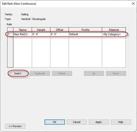
Edit Rails (Non-Continuous) Dialog Box
- Next you will adjust the balusters to stop at the bottom rail.
Click on the Edit… button next to Baluster Placement.
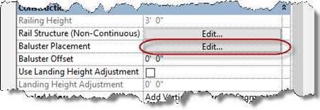
Edit… Button for Baluster Placement
- The Edit Baluster Placement dialog box opens.
Change the Base Offset setting for the main pattern of the balusters to 0′-4″. Also change the start, corner, and end post base offsets to 0′-4″.
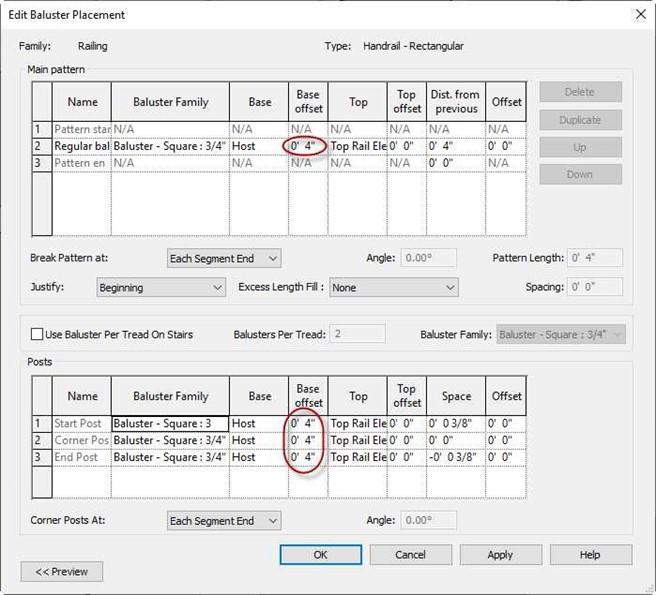
Edit Baluster Placement Dialog Box
- Change all four rails to the new rail type.
- Return to the railing at the top of the second floor.
Select the railing and change the railing type to Handrail – Rectangular (2 Rails).
-
Create a new railing type that has a Newel Post at the end of the rail. Set the base offset of the Newel Post
to 0′ 0″.
Name the new rail type Handrail – Rectangular (2 Rails) w/Newel Post.
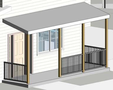
Rails Changed to New Type
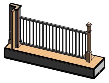
Railing Added at Bottom of Rectangular Railing
-
Change the Design Option to Main Model. The Option #2 elements will turn off.
Later you will set up a 3D view that will show this option.
- This is the end of Part 1. Save your file as RL6-1.


