
Creating the Second Floor and Garage Roof Design Options
Now you will set up the two Roof Design options. One of the options will be the Hip roof that you already have created. Option #2 will be the Gable roof.
- Open the RL6-1 file. Save the file as RL6-2.
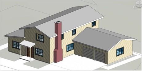
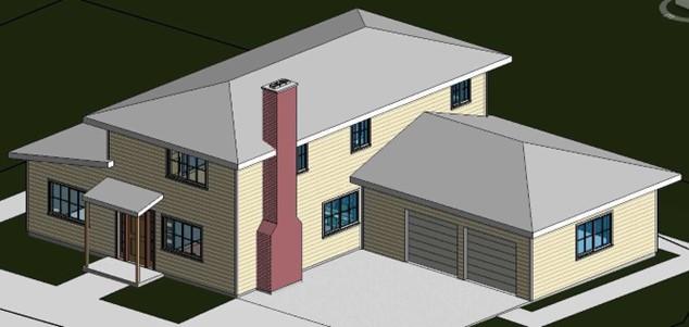
- Zoom out in the 3D view so that you can see the entire house.
You may wish to hide the trees, people and car to see the house clearly.
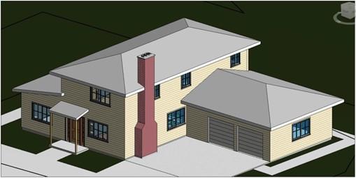
3D View of Entire House
- Before modifying the roofs, you will need to select the following elements:
- All the interior and exterior walls.
- The three roofs.
- The chimney.
- To select the elements:
- Draw a fence around the entire house in the 3D view there will be approximately 300 elements.
- Click on the Filter tool and click the Check None button.
- Check the boxes next to the Roofs, Wall Sweeps, and Walls categories. There will be approximately 70 elements.
- Hold down the Ctrl key and select the Chimney
Note: The reason for picking so many elements are that any elements that are hosted or connected to an element that is part of the design option must also be chosen. For example, even though the baseboards are not going to be changed, they need to be picked because they are being hosted by the walls.
- Add the elements to the Roof Option Set.
If you receive an error message, open the second floor view.
Check that the top edge of the closet door in Bedroom #3 is not too close to the north exterior wall.
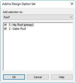
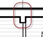
Closet Door Edge in Bedroom #3 Add to Design Option Set
- Click on the Active Design drop- down and choose Roof Option #2 (Gable Roof).
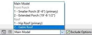
Option #2 (Roof) Chosen
- Select the first roof, click on the Edit Footprint tool and remove the slopes for the east and west side of the roof.
After modifying the roof you will need to attach the east and west exterior walls to the roof.
Since the walls were split, select all of the walls that are under the roof.
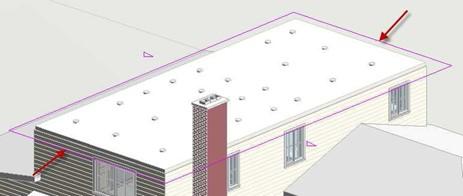
Second Floor Roof Footprint
- Select the garage roof, click on the Edit Footprint tool and remove the slope for the north side of the roof.
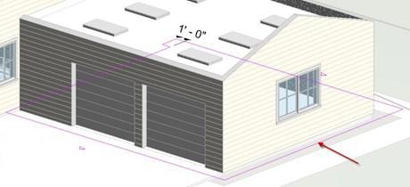
Garage Roof Footprint
- When completed your roofs will look like this…
You will need to re-paint the gable end fascia boards with the Paint – White material.
Roofs Modified
- Return to the Main Model.
Adding Corner Trim to Walls
In this next section, you will add corner trim at all wall corners of the building. This will be part of the Main Model and not the Design Options.
- Open the First Floor view.
- Zoom in on the wall corner at the northwest corner of the garage.
- Click on the Component Model In-Place tool. Select the Generic Models family category.
- Name the Family, Exterior Corner Wall Trim.
- Use these dimensions for the shape of the trim.
Click the green check when finished.
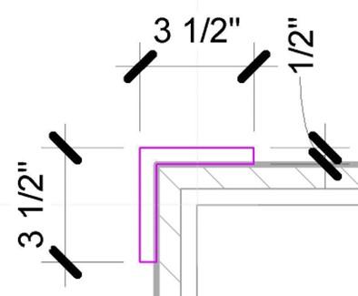
Exterior Trim Dimensions
- Set the material to Plastic.
Change the color to light gray (RGB 242 242 242).
Also in the Graphics tab check the Use Render Appearance checkbox.
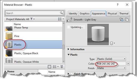
Material Changed to Plastic, Color Changed to Light Gray
- Click the green check to fish the component. Open the North Elevation view.
- Zoom in to the corner trim and click on it.
You will see arrows at the top and bottom of the extrusion.
Click and drag on the arrows to the top and bottom of the clapboard siding.
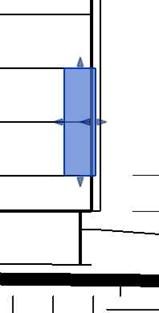
Arrows on Extrusion
- Open the First Floor view and copy the extrusion to the other corners of the building.
Open each elevation view and adjust the height of the trim.
- Select the trim at the northwest corner of the garage. Copy the trim to clipboard.
- Open the Second Floor view. Paste the trim, select the Aligned to Current view option when pasting.
The trim will appear at the same relative location in the view.
-
Move the trim to the upper left corner of the second floor walls. Copy the trim to the southwest and southeast corners. You will not need to copy the trim to the northeast corner.
- Open the West Elevation view and adjust the second floor trim to the correct height.
The trim is added to the building.
Trim Added to Wall Corners
Setting Up the Views of the Design Options
Next you will create 3D views that will show the two sets of Design Options.
-
Duplicate the 3D view and rename it: Front Porch 1 –
Roof 1.
Setup a cropped view that shows the entire house.

Cropped View
- Duplicate the view three times.
Refer to the chart below for the names of the views and the Design Options to be shown.
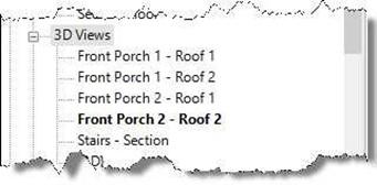
3D Views Created
|
View Name |
Design Option |
|
|
Front Porch Option |
Roof Option |
|
|
Front Porch 1 – Roof 1 |
Option #1 |
Roof #1 |
|
Front Porch 1 – Roof 2 |
Option #1 |
Roof #2 |
|
Front Porch 2 – Roof 1 |
Option #2 |
Roof #1 |
|
Front Porch 2 – Roof 2 |
Option #2 |
Roof #2 |
-
To set the Design Option for each view, open the Visibility Graphics Overrides dialog box
by pressing the “V” key twice (VV).
Click on the Design Option tab on the right.

Visibility Graphics Overrides Dialog Box
- Re-open the dialog for each view and set the Design Option display by clicking on the <Automatic> text.
When you put together the portfolio, you will place the four views on a single sheet.
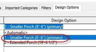
Design Option Selected
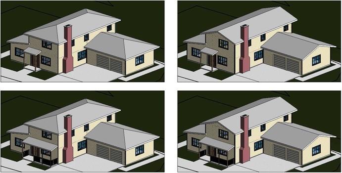
Design Option Examples
- This is the end of Part 2. Save your file as RL6-2.


