
EAST/NORTH ELEVATIONS
, SOUTH/WEST ELEVATIONS
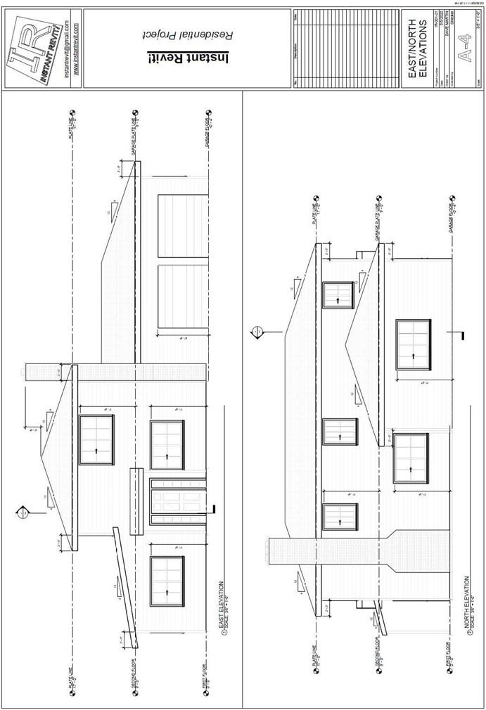
East and North Elevations
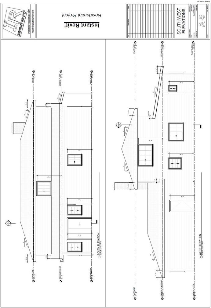
South and West Elevations
Creating the Sheet Views
- Open the RL7-4 file. Save the file as RL7-5.
- Open the East Elevation view.
- Hide the categories for the People, Landscaping, and any other elements that should not be on the view.
- Turn on the Crop Window and adjust it to the edges of the view and to the Garage Floor level. Set the detail level to Fine.
- Rename any levels so that the text is all caps. Rename the corresponding views as well.
- Some of the level text will change to two lines.
Update the Level Head – Circle family to stretch the text window.
- Go to the Families section in the Project Browser.
Expand the Families section if needed. Expand the Annotation Symbols.
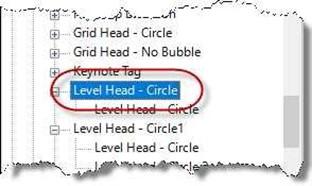 Scroll down to the Level – Circle family
- Right click on the family and select Edit.
The family will open as a separate file.
Level Head – Circle Family
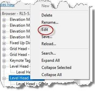
Edit Choice
- The family will open as a separate file. Click on the Name text.
Stretch the box to the left for the text to approximately double the length.

Text Box Stretched
- Click the Load into Project button and overwrite the existing version.
- Now the level text is one line in height.
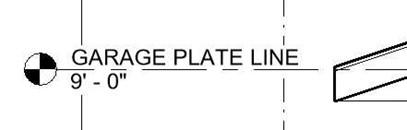
Updated Level Text
- Add the slope symbol to the roof surfaces.
Set the slope symbol to Triangle and
the Offset from Reference to 1/8″.
When placing the symbol, you will need to press the tab key to cycle through the different roof surfaces.
Add the slope symbol to roof surfaces on the other three elevation views.
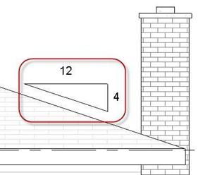
Slope Symbol Placed
- Open the Material Browser dialog box and select the Asphalt Shingle material. Click the Model selection to find the material.
Set the Surface Pattern to Block 8×16 and the color to light gray. This will simulate the tile surface of the roofs.
Also change the Siding, Clapboard material to light gray.
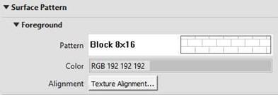
Surface Pattern Settings
- The default settings for the elevation views shown the edges of the view with a thin line weight. Before setting up the sheets, you will modify the line weight for the roof edges, wall edges, window trim, and door trim.
Open the Visibility Graphics Overrides dialog box.
-
In the Model Categories tab set the following Visibility categories to a line weight of 6:
Doors – Frame/Mullion and Trim, Generic Models – Trim, Roofs, and Walls. For the Generic Models and Doors visibility click on the “+” symbol to expand the category.
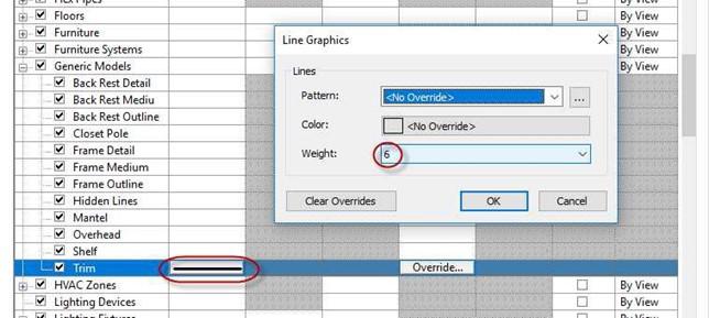
Generic Models Line Weight Set to 6
- After changing the East elevation view, create a View template called; Exterior Elevations.
Apply this template to the other three exterior elevation views.
- Add dimensions for the tops of the windows and doors.
Also add dimensions for the roof overhang. You will need to hide the plastic trim at the wall corners.
-
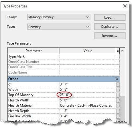
Since the Plate Line level was lowered to 17′-0″ earlier, you will need to lower to top of the chimney 1′-0″. Change to the 1-Hip Roof design option and then select the chimney.
- Click the Edit Type button and then change the Top Of Masonry parameter to 23′-0″.
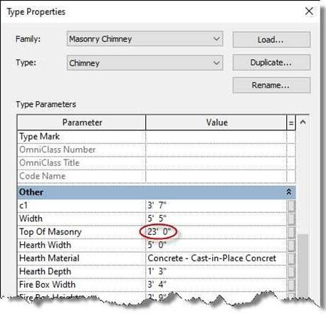
Top Of Masonry Parameter
- Also dimension the top of the chimney to the roof ridge. You will need to change from the Main Model to the Hip Roof (Primary) option.
- Use the Linework tool in the Modify tab to thicken the lines at the edge of the chimney.
- Create two sheets for the four elevation views.
- The scale of the elevations is 3/8″ = 1′-0″.
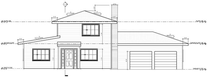
East Elevation with Line Weights Applied
- Drag and drop the East and North Elevations onto the first sheet and the South and West Elevations onto the second sheet. Position the views in the center of each sheet.
- Change the names of the elevation views to all caps and add the word Elevation.
- Draw a medium detail line that divides the sheets in half.
- Starting with the View Title.rfa file, create a new family for the view title.
Name the family View Title – Medium Text.rfa.
-
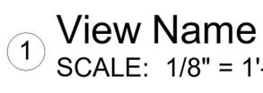 Change the text size for the title of the
view to 3/16″.
Add the word scale in front of the scale label.
- Load the family file into the drawing.
- Create a new Viewport type called Title w Line – Medium Text.
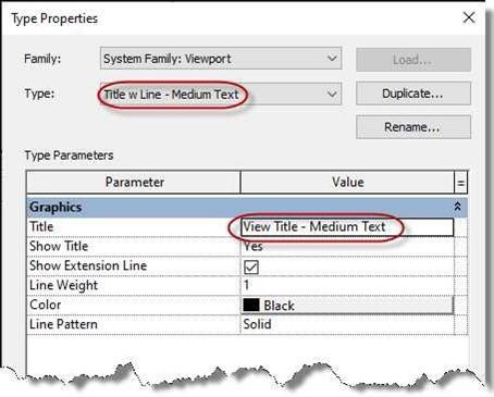
View Title – Medium Text.rfa
- Use the new type for the view labels for both sheets.
- After placing the views line up the view labels.
- This is the end of Part 5. Save your file as RL7-5.


