
Adding the Room Tags, Stairs, Basement Casework, RCP, and
Lighting
Adding the Room Tags
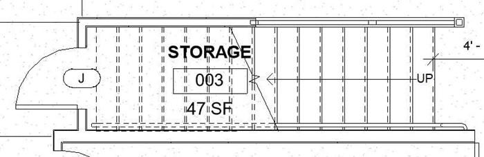
Now that you have completed the walls and placed the doors and windows, you will now add the room tags for the basement. Since this area is below the first floor, the rooms will be labeled 001, 002, 003, etc… There will be a total of four rooms and spaces.
- Open the RLA-3 file. Save the file as RLA-4.
- Open the Basement Floor Plan.
- Click on the Room, tool in the Architecture, Room & Area panel.
- Create rooms as shown in the drawing.
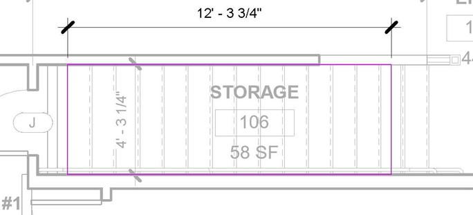
You will create the Storage Area under the stairs after adding the stairs. You may also wish to update the dimensions; some have been added and/or changed.
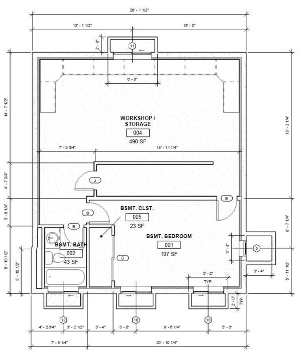
Basement Floor Plan with Room Tags
Adding the Stairs and Creating the Stairwell Opening
In this first section you will add the stairs that lead from the first floor to the basement. They will be directly beneath the first floor stairs and will replace the first floor storage area.
- Open the RLA-3 file. Save the file as RLA-4.
- Open the first floor view.
- Select the stairs and copy to clipboard. Paste the stairs to the basement floor level.
After pasting, move the stairs 12″ to the right.
- Create an interior elevation view in the work/storage area on the north side of the basement. Point the view toward the stair.
-
Modify the profile of the north stairwell wall to create a 6″ high surface above
the treads of the stair nosing.
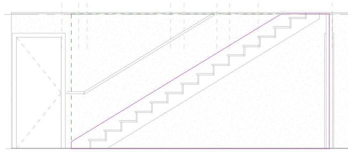
Basement Wall Profile Modified
- Add a Rectangular Railing w/Newel Post railing type on top of the wall.
Pick the wall as the host and being the railing at the top and draw in a downward direction.
- Open the interior elevation and adjust the wall profile to support the bottom of the newel post.
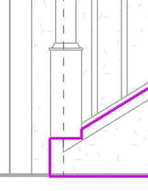
Wall Profile Modified for Newel Post
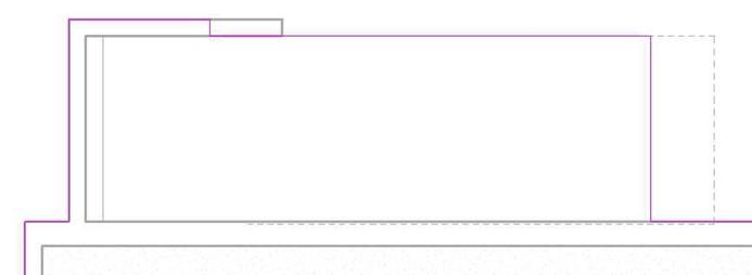
- To create the floor opening open the first floor view.
Select the floor and change the transparency to 50.
- Edit the boundary and create a rectangular opening the begins at the first riser on the left.
The length p
Floor Opening for Basement Stairs
- Return the floor to zero transparency.
- Remove the Storage space (Room 106) on the first floor.
The easiest way to do this is to open the Room Finish Schedule and delete the row for the room.
- Before adding the casework and furniture, add the storage area under the basement stairs.
- First add a room separator at the 4th riser from the bottom of the stairs. This should reduce your workshop/storage square footage to approximately 444 sq ft.
- Add the room below the stairs.
Basement Storage Room Added
Adding the Basement Casework and Furniture
In this part you will place the casework (cabinetry) in the Work/Storage Area. You will also place the furniture in this area and the Bedroom area.
- Open the Basement Floor view.
You will add a row of cabinets across the north wall of the basement. Reduce or increase the cabinet and/or filler width as needed. Keep all cabinets the same size.
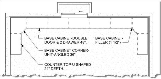
Cabinet Layout on North Basement Wall
- Place the furniture.
Refer to the chart and drawing for the furniture names and locations.
|
Family Name |
Where Located |
|
Basement Bedroom |
|
|
Dresser – Modified 48″ x 60″ x 24″ |
Loaded Previously. |
|
Bed-Standard King 78″ x 80″ |
Included with template. |
|
Table-Night Stand 24″ x 24″ x 30″ |
Loaded Previously. |
|
Workshop Storage |
|
|
Desk 60″ x 30″ |
Furniture, Tables folder. |
|
Chair-Executive |
Furniture, Seating folder. |
|
Shelving 96″ x 12″ x 84″ |
Furniture, Storage folder. |
|
F0230 – Chair, Drafting, Rotary |
Custom Families Furniture folder. |
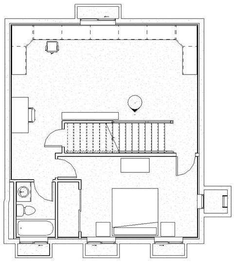
Basement Floor Furniture Plan
Adding the Reflected Ceiling Plan and Lights
In this section you will add the ceiling and lights to the basement rooms and stairwell.
- Open the Basement Floor Ceiling Plan view. This view was created automatically when the Basement Floor level was created.
- Hide the elements for the Topography, Section Marks, Property Lines, Furniture, and Reference Planes.
- Open the View Range dialog box.
Set the view range as shown.
Note: If some of the walls are not visible, check the wall’s height. Exterior walls are set to the Top of Basement Wall Level and interior walls are set to an Unconnected Height of 8′-1″.
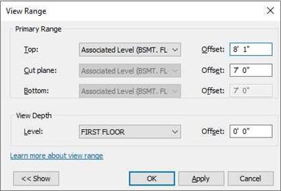
View Range Settings for Basement Ceiling Plan
-
Hide the footers and floors for the first floor, front and rear porches, garage, and
driveway slab.
You may also need to hide other elements as well.
- Click on the ceiling tool and add a GCB on Wood Furring ceiling type to each room.
Do not add a ceiling in the pipe chase area at the lower left corner of the plan.
- Select the Workspace area ceiling and create an opening for the stairs.
Area to be Removed from Ceiling
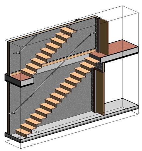
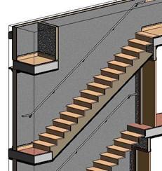
3D Section View of Basement Stairwell
- Create a new 3D section view that shows the basement stairs and a portion of the first floor stairs.
Note that the baseboard on the first floor wall needs to be removed in the stairwell. Click on the baseboard and drag it to the first floor stair riser. You will also need to paint the floor edge with the Gypsum Wall Board material and make the lines that separate the floor and walls invisible. You will need to change the design option to make the first floor wall’s lines invisible.
-
Save the view as Basement Stairs – Section. Adding the Ceiling Under the First Floor Stairs
1. Next you will add the ceiling under the first floor stairs. This must be done to add lights in the stairwell. Since the surface of the ceiling is sloped, you will add a Slope Arrow to the sketch.
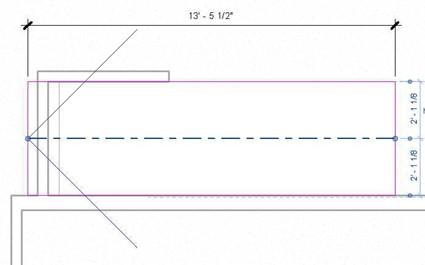
Drawing the boundary for the ceiling on the basement ceiling plan view. The sketch will begin at the edge of the main ceiling on the right and will extend 13′-5 1/2″ to the left.
The Slope Arrow will be added and set to the settings in the Properties dialog box.
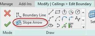
Slope Arrow Tool
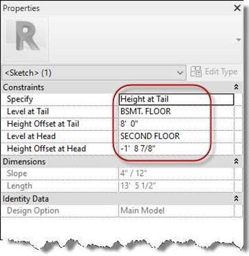
Slope Arrow Settings of Ceiling
Slope Arrow Placed on Ceiling Sketch Ceiling in 3D Section
Adding the Lights for the Basement and Stairs
- Open the Basement Ceiling Plan view.
- Use the Downlight – Recessed Can 8″ Incandescent – 120V type for the bedroom, bathroom, closet, and entry areas, and stairwell lights.
Use the Troffer Light – 2×4 Parabolic 2’x4′(2 Lamp) – 120V type for the Work Area/Storage area.
See drawing for locations.
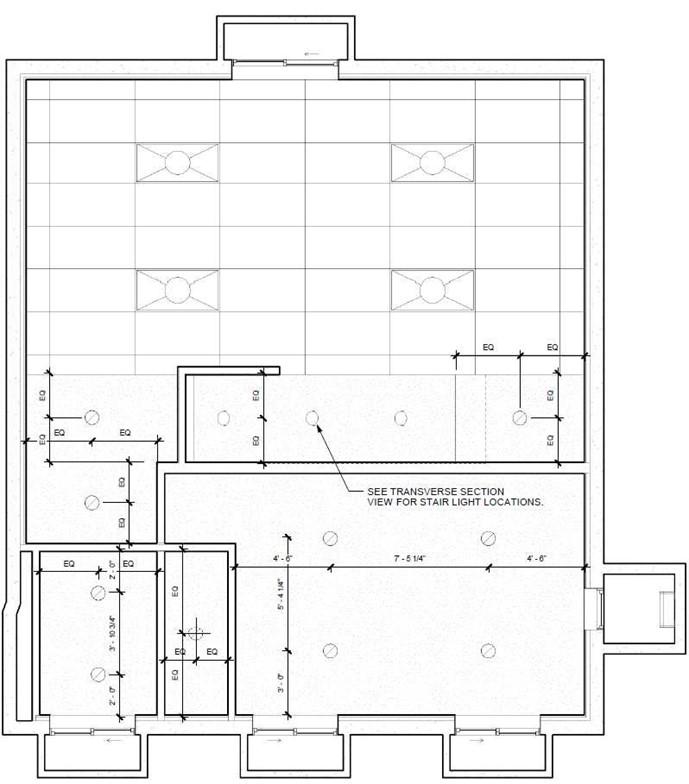
Basement Light Locations
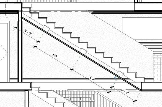
- To place the stairwell lights. Place the lights along the sloped surface in the Ceiling Plan view. Draw a horizontal reference plane at the midpoint of the stairs. Lock the lights to the reference plane using the Align tool.
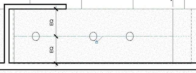
Recessed Can Lights Placed on Sloped Ceiling
- Open the Transverse Section view.
- Draw five reference planes perpendicular to the celling.
- Locate to left and right planes at the beginning and end of the ceiling surface.
Draw three additional planes for each light.
- Dimension the planes as shown.
- Align the lights to the planes.
Lights Aligned to Planes
- Open the Basement Ceiling Plan to check the location of the lights.
Add the note for the stairwell lights.
- This is the end of Part 4. Save your file as RLA-4.


