
Adding the Interior Walls, Bathroom Fixtures, Doors, and Windows
Adding the Interior Walls and Bathroom Fixtures
In this first section you will add the interior walls for the Bedroom, Bathroom, and Workshop/Storage area. You will also create walls for the windows around the outside edges of the exterior walls.
- Open the RLA-2 file. Save the file as RLA-3.
- Refer to the example on the next page for the wall types and location.
You will need to create another exterior wall type without the insulation and gypsum board.
Name the wall type Basement Wall – 8″ Concrete.
- Open the First Floor view.
- Select the bathroom fixtures and cabinets. Copy to clipboard.
- Open the Basement Floor view and paste to the current view.
- The fixtures and cabinets will land too far to the left. Re-position them to the right.
-
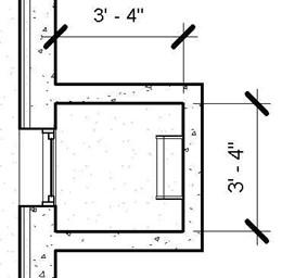
Due to the thickness of the exterior wall, you will need to change the size of the basement bathroom. Adjust the north and west walls to the new size as shown in the diagram.
Also move the closet wall to the left to maintain a 3′-4″ size.
-
Next you will add the doors and windows. Use the charts below for the types and sizes.
Note: You should add tags and dimensions after this part of the tutorial.
|
Door Letter |
Door Type and Size |
Notes |
|
B |
Single-Flush 32″ x 80″ |
This size has been created. |
|
D |
Sliding-Closet 72″ x 80″ |
Size is included. |
|
J |
Single-Flush 30″ x 80″ |
Size is included. |
|
Window # |
Window Type and Size |
Notes |
|
9 |
Window-Double-Hung 34″ x 58″” |
This size will need to be created. |
|
10 |
Window-Sliding-Double 48″ x 36″ |
This size will need to be created. |
|
11 |
Window-Sliding-Double 60″ x 36″ |
This size will need to be created. |
|
12 |
Window-Sliding-Double 48″ x 18″ |
This size will need to be created. |
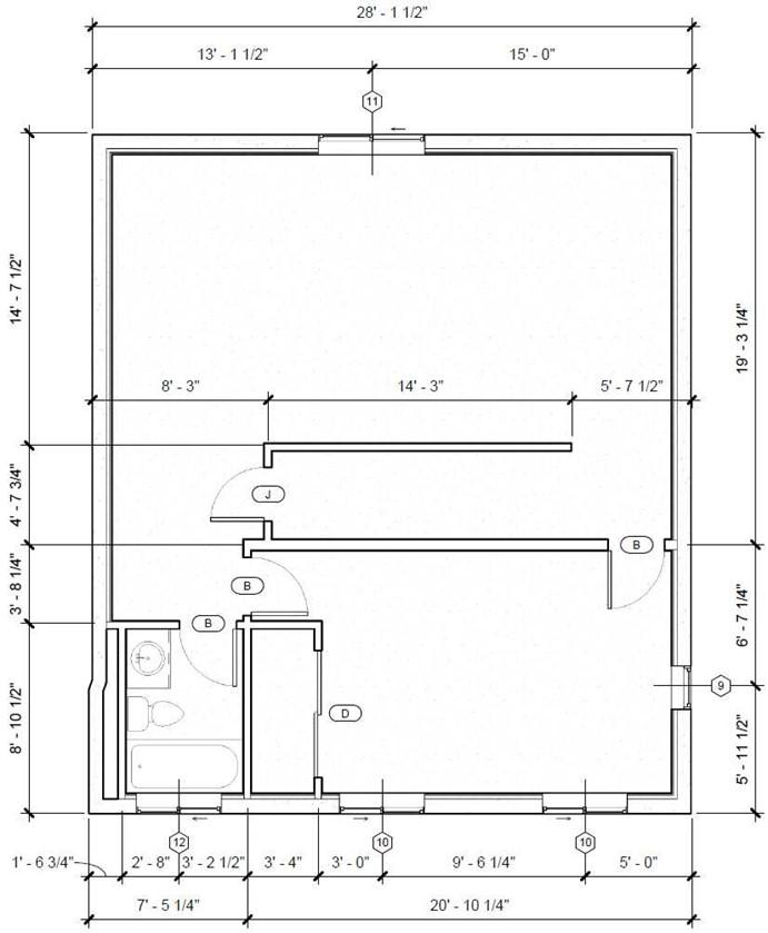
Updated Wall, Door, and Window Locations
Adding the Window Wells
Window wells are needed for each window because most of each window is below ground level. The window well is used to allow for natural light to come through the window. One of the windows will also be used as an alternate escape route.
- Zoom in on the window at the top of the basement area.
- Create a new wall type called Basic Wall – Window Wall Wells – 4″.
- Draw three walls around the window as shown.
The top constraint of the walls is First Floor and the bottom constraint is BSMT. FLR. With base offset of 3′-7″.
Add a 4″ thick gravel floor around the inside edge of the walls. The level for the floor is BSMT. FLOOR and the height offset from the level is 4′-1″.
Note: You use the sand pattern for the gravel material. There is also a custom gravel .PAT file in the custom families folder.
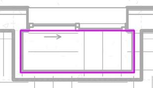
North Window Well Dimensions
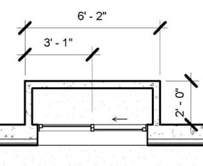
- Draw the walls for the other three windows on the south side of the basement. The dimensions for all three windows are the same.
Beginning with the left window, the top constraint is the FIRST FLOOR level with a top offset of -1′-0″. The base constraint is the BSMT. FLOOR level with a base offset of 5′-1″. The floor height level is BSMT. FLOOR with a base offset of 5′-7″.
The next two window walls are the same except the base offset is 3′-6″. The floor height level is BSMT. FLOOR with a height offset of 4′-1″.
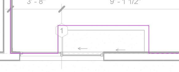
South Window Well Dimensions
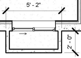
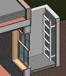
- The last set of walls will be for the emergency egress window located on the east wall. Instead of 4″ thick walls you will use 6″ thick walls. The depth of the window well is deeper to allow a person to escape through the window and climb a ladder to safety.
The top of the walls is the same as the south window wells. The base constraint level is BSMT. FLOOR and the base constraint 1′-6″. The floor height level is BSMT. FLOOR with a height offset of 2′-3″.
Emergency Egress Window Well Dimensions
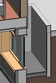
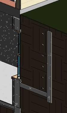
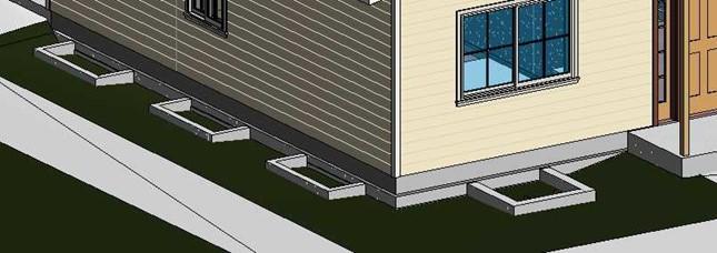
Shown below are the 3D section views of the window well for the three window wells.
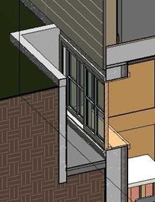
South Window Well
North Window Well
East Window Well (Emergency Egress)
- To add the ladder for the east window well you will first need to load the family from the Residential Families (2021) folder.
The name of the family file is
Ladder-Precision_Ladders-Tubular_Ladder_to_Roof_Hatch_No_Cage.rfa and the family file is in the root folder. The file name was not changed from when it was obtained from the manufacturer.
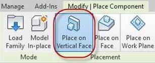
- When placing the ladder confirm that the Place on Vertical Face toggle is turned on.
Ignore the error message regarding the Instance Origin.
Place on Vertical Face Toggle
-
The default height of the ladder is 20′,
change the parameters to the following.
After placing the ladder you may select it and then press the Edit Type button to find out more information about the manufacturer.
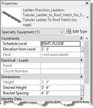
Ladder Parameters
You may have noticed that the walls for the emergency egress window are below the surface of the topography. You will modify the contour of the topography to lower the surface below the tops of the walls.
Also, the earth is filling the window wells. You will use the Building Pad tool to remove the earth. You will need to place five separate pads, one for each window well.
Earth Filled Window Wel
-
Open the Site Plan view. Select the topography and change the transparency to
50. Now you can see the window well walls. Also set the cut plane to 4′-0″.
Select the topography and the click the Edit Surface tool.
Add and change the following points on the south side of the house as shown.
New and Changed Points to the Topography
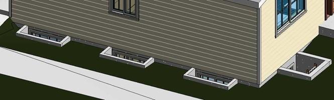
- Now the tops of the window well walls are visible.
Tops of Window Well Walls Visible
- Next you will add the building pads for each of the window well.
Open the Site Plan view. Set the cut plane to -2′-0″.
- Click on the Building Pad tool in the Model Site panel.
Starting from the bathroom window, the pad height offset is 5′-6 for this window, the next two south windows have an offset of 4′-0″, the east window is 1′-11″, and the north window has an offset of 4′-0″. All these windows have the offset based on the BSMT. FLOOR.
-
When drawing the pad boundaries set
the offset setting to 1/2″.
This will place the edge of the pad boundary 1/2″ into the concrete wall. This will keep the earth material from bleeding through.
Move the line on the side of the boundary that faces the exterior wall so that it overlaps the exterior wall face.
One pad cannot overlap another pad boundary.

Offset Set to 1/2″
Pad Boundary
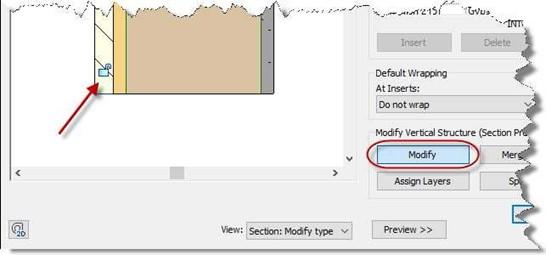
- The last thing is to change the exterior walls so that the exterior siding and plywood extends down to the top of the foundation wall.
Select the south exterior wall and then click the Edit Type button. Click the Modify button and unlock the two outside layers of the wall.
Wall Layers Unlocked
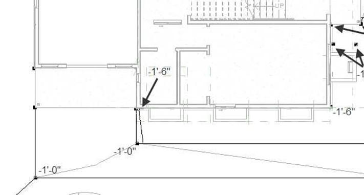
- Select the south and east walls and change the base extension distance to -1′-0″.
- Lower the corner trim 1′-0″ at the southeast corner.
Exterior Layers and Corner Trim Lowered
- Open the First Floor view. Set the bottom and view depth settings to -2′-0″. This will allow you to see the window well wall for the north basement window.
- Select the edge of the driveway and pick the Edit Boundary tool.
Create a notch in the driveway slab around the outside edge of the window well walls.
Driveway Slab Notch
- This is the end of Part 3. Save your file as RLA-3.


