
Adding the Basement Walls, Footers, and Floor
- Open the RLA-1 file. Save the file as RLA-2.
- Before adding the Basement walls, you will need to create a new wall type.
Starting with the Foundation – 10″ Concrete type, create a new wall type called Basement
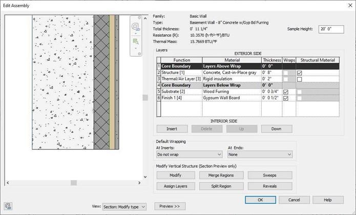
Basement Wall Layers
- In the BSMT. FLOOR view, draw the basement wall
around the perimeter of the first floor.
Align the outside edge of the concrete surface with the face of the core of the first floor walls.
Draw reference planes around the perimeter to make it easier to locate the walls.
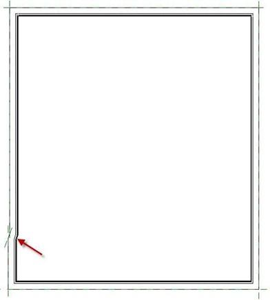
There is a 2″ jog at the bottom left corner of the walls.
Basement Walls Placed
-
Create a wall type called Foundation – 18″ Concrete. Start with the Foundation
– 10″ Concrete type.
Set the view range Bottom and View Depth Level to -1′-0″. This will make the
footer visible.
- Create a new view for the T.O. BSMT. FTR. This view will be used when placing the footer walls.
Hide any extra elements that are in the view.
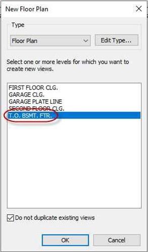
New Floor Plan Dialog Box
- Draw the new wall type centered on the center of the concrete portion of the foundation wall. Set the top constraint to T.O. BSMT. FTR. And set the bottom to the B.O. BSMT. FTR. This will give a total height of 8″.
Set the location line for the footer wall to Finish Face Exterior and the Offset to
4″.
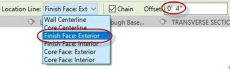
Location Line and Offset
Adding the Floor
For this section you will add a concrete floor at the bottom of the basement and modify the basement walls.
- Create a new floor type as shown below.
Begin with the Concrete, Sand/Cement Screed material to create the Sand material.
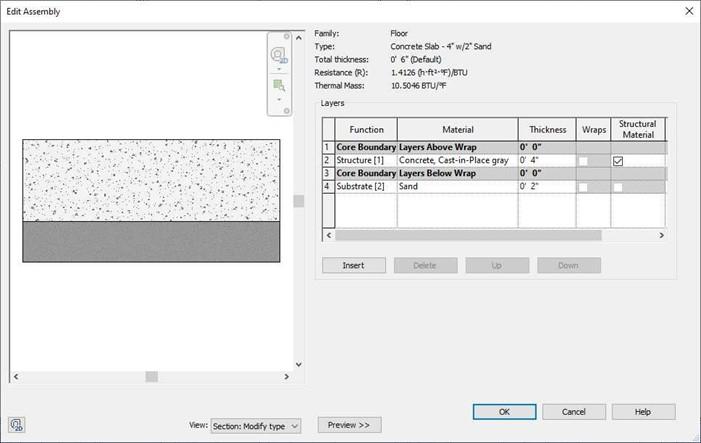
Basement Floor Layers
-
Open the BSMT. FLOOR level. Click on the Floor tool.
Set the offset for the floor edge to 2″ and click around the edge of the
basement walls.
Uncheck the Extend into wall (to core) checkbox.
This way the concrete floor will not join to the concrete walls.

Offset and Extend into Wall (to core) Settings
- After selecting the walls, answer no to the alert box regarding joining the walls to the floor.
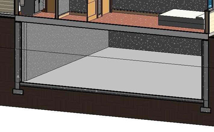
- Open the Transverse Section view.
You will modify the basements walls to move the gypsum wall board, wood furring, and rigid insulation layers about the basement floor.
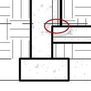
Layers Below the Floor Level
- Select one of the basement walls then click the Edit Type button.
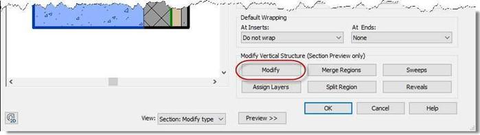 Edit the structure of the wall and zoom in on the bottom of the wall. Click the Modify button
Edit Assembly, Modify Button
-
After clicking the modify button, click on the horizontal line below the three layers on the right side of the wall.
A padlock will appear. Mouse over the padlock until it changes yellow. Then click on it to open it.
Repeat for all three layers.
Yellow Padlock
- Click on the wall and set the Base Extension Distance to 1′-0″.
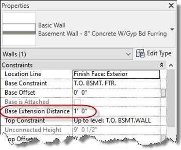
Base Extension Distance set to 1′-0″
- Now the inner layers of the wall are above the top of the floor.
Open the Basement Floor level and repeat the process for the other basement walls.
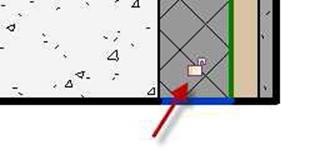
- You may notice at the corners that the inner layers are not meeting at the corner.
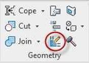
To fix this, click on the Wall Joins tool in the Modify, Geometry panel.
Click on the wall corner and then select the Miter bottom to change the join style.
Changing the Topography for the Basement Area
Layers Above Floor
Wall Joins Tool
For this section you will create an opening in the topography that will surround the basement walls and go as deep as the floor.
- Open the Site Plan view.
If the reference planes are not visible, unhide the ones that you used to locate the basement walls.
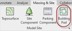 Click on the Building Pad tool in the Massing & Site, Model Site panel.
- Click the reference plane lines to create the boundary.
Click the Green Check when finished.
Building Pad Tool
Pad Boundary Sketch
 Open the Transverse Section view.
The pad begins at the First Floor level
and is 1′-0″ thick.
Edit the pad to make it 1/4″ thick.
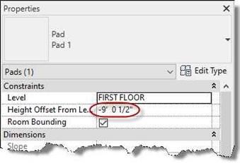
Change the Height Offset From Level
to -9′ – 0 1/2″.
Hide the Pad when you are finished. Pad Height Offset Setting
- Open the 3D view and check the Section Box checkbox.
- Adjust the section box to see the area under the first floor. The basement area is now free from earth.
Basement Area Cleared
- This is the end of Part 2. Save your file as RLA-2.


