Curved Ramp Supported by Curved Wall
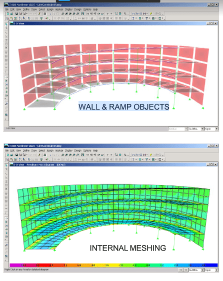
This example, Figure 2, illustrates the use of Line Constraints to capture the interaction of
a curved shear wall supporting a curved ramp. Notice that there are no joints at the points
where the ramp element edges intersect the wall element edges. Displacement
compatibility along the lines of intersection of the ramp and the wall is enforced
automatically by the generation of Line Constraints along those lines. Notice how the
application of Line Constraints allows the wall and ramp mesh to retain a simple
rectangular (or quadrilateral) configuration. A conventional finite element model would
be very irregular because it would need all the additional joints (and corresponding
elements) to allow for the ramp element and wall element edge intersections.

Figure 2: Curved Ramp Supported by Curved Wall


