
Floor Slab – Shear Wall Compatibility
This example, Figure 3, illustrates a 3D Concrete Flat Plate Building with shear walls and
an elevator core. Again, in this model, Line Constraints automatically appear at the lines
where the floor and wall objects intersect. This, of course, as in previous examples, will
enforce displacement compatibility when mesh geometries do not match. As shown in the
deformed shape of the Elevator Core, in many places the wall meshing does not match
the floor meshing. All elements meeting at common edges, however, still show no
displacement incompatibilities, even though the element nodes do not coincide.
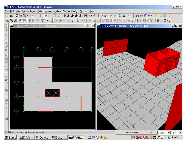
Figure 3: Floor Slab – Shear Wall Compatibility
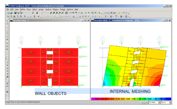
Shear Wall – Spandrel Transition
This example, Figure 4, models a Shear wall – Spandrel System, illustrating mesh
transitioning from the spandrel to the shear wall. Line Constraints are generated as
needed in any direction. In this case the Line Constraints are vertical as well as
horizontal.
WALL OBJECTS INTERNAL MESHING
Figure 4: Shear Wall – Spandrel Transition


