
Lighting Plan
This project is a drawing of a lighting plan for a rectangular room. The view of the room is a reflected view of the ceiling of the room. This view also includes the lights that are recessed into the ceiling material. This project will introduce the student to the creation of Groups, use of Dimensions to constrain the model, and the use of the Region tool to create a filled region.
Starting the Tutorial
- If needed, Start Revit 2021 by clicking on the icon on the desktop.
- Open the last version of the Warm Up project, WU1-5.
- Save the file as WU2-1.
Creating the Outside Boundary and Filled Region
- Click on the Drafting View tool in the View tab, Create panel.
- Name the New Drafting View, LIGHTING PLAN and set the scale
to 1/4″ = 1′-0″.
- Using the Detail Line tool, draw the outside of the four walls.
Use the Wide Lines style.
Outside of the Four Walls
- Next you will draw the boundary of the filled region.
Click on the Region tool in the Annotate tab, Detail panel.
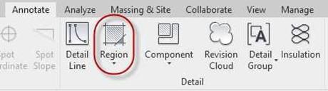
Region Tool
- Click on the Edit Type button in the Properties Box.
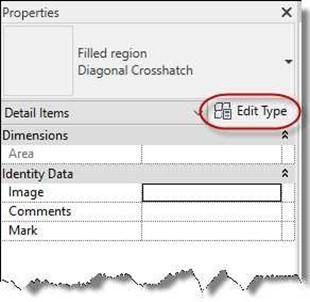
Edit Type Button
-
In the Type Properties Dialog, click on the Duplicate button. Name the new region Gypsum.
Name Dialog
- After the region is created, click in the box to the right of the fill pattern.
Click again on the small button with the “…” inside.
This will open the Fill Patterns dialog.
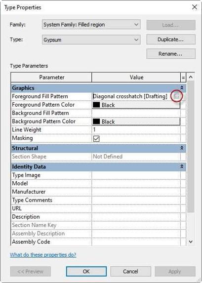
Type Properties Dialog
- Select the Drafting button (if needed) and then select the Gypsum-Plaster material. Press the OK button to close the box.
- Back in Type Properties, click the box next to Foreground Pattern Color.
Select the light gray color as shown.
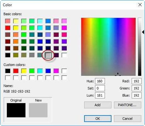
Color Dialog
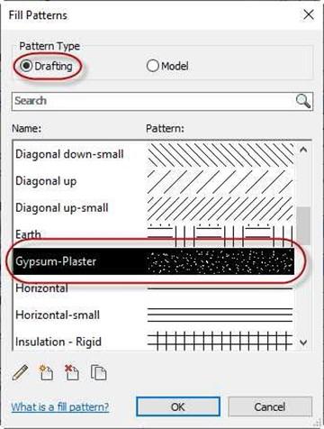
Fill Patterns Dialog
- Click the OK button to close the Type Properties dialog box.
 Set the Line Style to Wide lines and draw a rectangular shape as shown. You do not need to match the sizes exactly.
Filled Region Boundary
- Click the Green Check to complete the boundary.
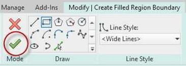
Green Check
- You will see that the inner rectangle is filled with gray stippling.
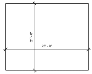
- Add dimensions to control the size of the inner and outer rectangles as shown.
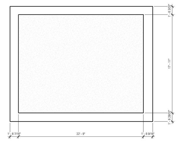
Dimensions Added
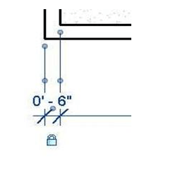
- Click on one of the edges of the inner rectangle. The dimension connected to the line will turn blue. Click on the dimension text and change it to 6″.
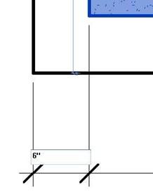
-
Repeat the process so that all four edges are 6″
from the outside edge.
As you change each dimension click on the dimension and lock it.
This will represent the walls of the room.
Dimension Changed
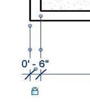
Locked Dimension
- Once the four 6″ dimensions are locked, click on one of the inner vertical lines and change the inner width to 25′-0″.
- Repeat the process for the horizontal lines.
The inner height will be 20′-0″.
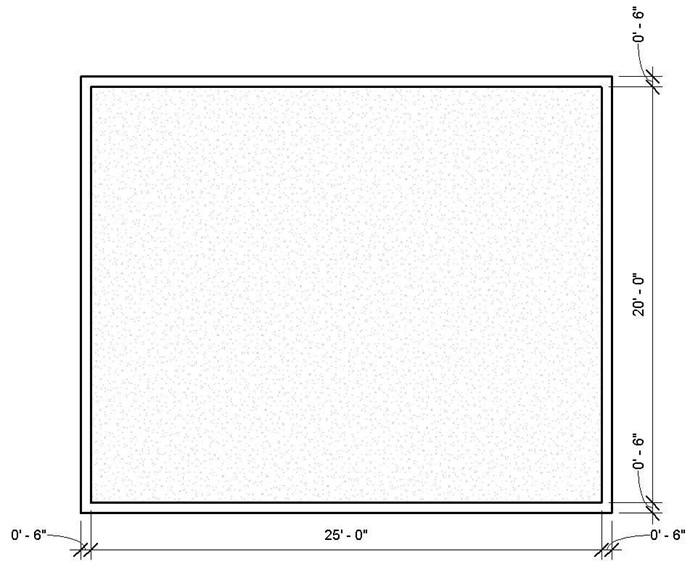
Final Wall Dimensions
- This is the end of Part 1. Save your file as WU2-1.


