
Base Plate
This first project of this textbook is of a one-view drawing of a part consisting of different geometric shapes. The student will learn the use of the Line tool, drawing shapes, use of the Dimension tool to place dimensions on the part, inserting the view onto a sheet, and printing the drawing to a PDF format.
Starting the Tutorial
- If needed, Start Revit 2021 by clicking on the icon on the desktop.
- Save the file as WU1-1.
Creating the Outside Shape
All three Warm-Up exercises will be contained in the same Revit file. To begin the first exercise, you will need to create a drafting view that will contain your drawing. All the warm-up exercises are in two-dimensional format and are designed to aid the student in learning the basic drawing tools of the program.
- Click on the Drafting View tool in the View tab, Create panel.
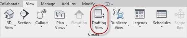
Drafting View Tool
- Name the New Drafting View, BASE PLATE and set the scale to 3/4″ = 1′-0″.
In the Project Browser you will also see a new view category called Drafting Views (Detail) with a new drafting view called SINGLE STORY HOUSE.
The bold text indicates it is the current view open.
You will also see a new view tab at the top of the drawing area named SINGLE STORY HOUSE
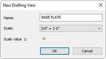
New Drafting View Dialog Box

New Drafting View in Project Browser
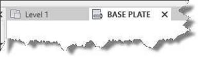
New View Tab
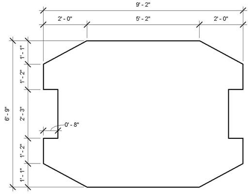
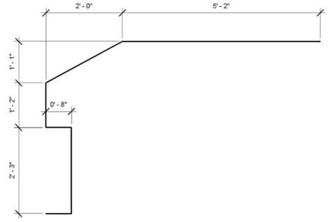
- You will begin by drawing the outline of the base plate. You will use Reference Planes to help you size the object.
Note: The dimensions have been increased in size for clarity and will be added later.
Outline of Part
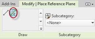
 Go to the Architecture tab and select the Ref Plane tool in the Work Plane panel.
Reference Planes are used as construction lines and anchor points for parts of the drawing. They may be left on the drawing and will not be appear on the drawing when printed.
 Add two reference planes as shown.
When adding the planes, you will have the option of naming them. You will not need to do this for this tutorial.
The lengths of the lines/planes will not matter.
Reference Plane Tool
Note: It may help to think of these
lines as construction lines. Reference Planes Added
- Click on the Pick Lines option to add the next lines.
- Set the first offset
to 1′-1″.
(You may type the value as 1 1)
- Hover (don’t click) over the horizontal reference plane.
Move the mouse slightly up to place the plane.
Click to place the plane.
- Repeat the process for the vertical line.
Use 2′ 0″ for the offset.
If the lines are not long enough, click on the line and stretch it using the circle handles at the ends of the line.
 Pick Lines Option
Offset Set to 1′ 1″

 New Ref Plane Added
Reference Plane Handle
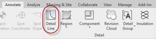 Click on the Detail Line tool and set the lineweight to Wide Lines. Snap the lines at the intersection of the Reference Planes.
Detail Line Tool
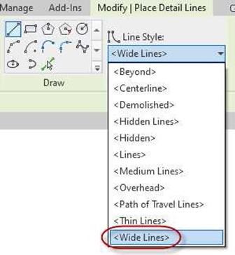
Lines Set to Wide Lines
 Use this method to setup the upper left corner of the Base Plate.
You may delete the reference planes when you are finished.
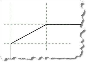
Detail Lines Added
Upper Left Corner of Plate
 You will use the Mirror tool to facilitate creating the outline. Select the four lines as shown.
Four Lines to be Selected
- Click on the Mirror – Draw Axis tool.
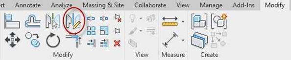
Mirror – Draw Axis Tool
- Snap to the midpoint of the upper horizontal line indicated by a magenta triangle. Drag down 90 degrees and click the mouse.
Note: The Snaps function is explained after this tutorial part.

Midpoint Snap
- The four lines are now mirrored to the right side of the plate.
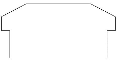
Four Lines Mirrored
- Repeat the process in the vertical direction. Pick the all the lines except for the two bottom vertical lines.
- Click on the Mirror tool.
- Midpoint snap on the bottom vertical line.
- Drag to the right and click the mouse.
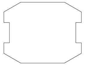 The top half is now mirrored.
- This is the end of Part 1. Save your file as WU1-1.
Outline Completed
Snaps Function
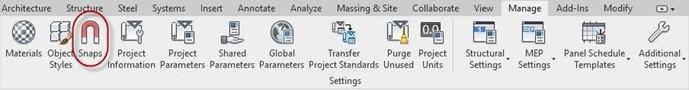
The Snap function is used to lock one object to another. To access the settings for the snap mode, click on the Manage tab and select the Snaps tool. This will open the Snaps dialog box which contains settings to control the length and angular snap increments, object snap modes, and temporary overrides.
The letters in parentheses next to each name mode are used to select the snap override.
To use the override, type the two letters after beginning the command. This way only the mode selected will be available during the command.
Once the command has ended, the snap mode override will be turned off.
Settings Panel
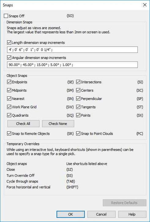
Snaps Dialog Box
You may also select the override by right-clicking in the drawing area while in the command.
Then select Snap Overrides and then choose the desired snap mode.
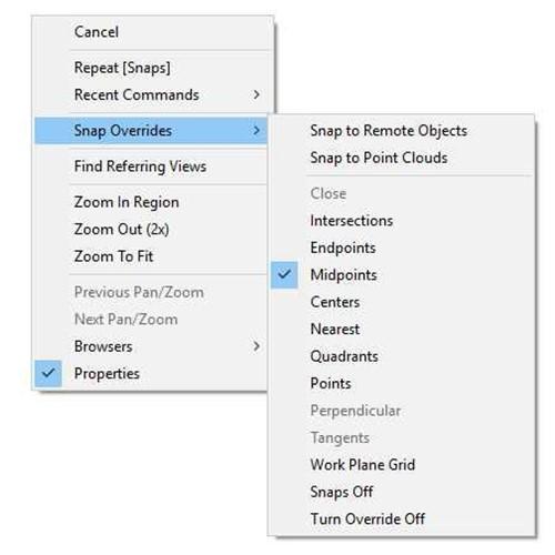
Snap Overrides


