Dimensioning
TOPICS
Introduction
Dimensioning components Dimensioning object’ s features Placement of dimensions.
Introduction
ENGINEERING DESIGN
PROCESS
Sketches of ideas
Design a part

Create drawings

Contractor or Manufacture
RESULT
Multiview Drawing
Dimensioning
TRANSFERRED INFORMATION
Shape,Size, Location
-
- Sizes and locations of features
- Material’s type
Non-graphic informationThese informations are such as:DEFINITION
Dimensioning is the process of specifying part’ s information by using of figures, symbols and notes.
DIMENSIONING SYSTEM
- Sizes and locations of features
-
Metric system : ISO and JIS standards
Examples 32, 32.5, 32.55, 0.5 (not .5) etc.
- Decimal-inch system
Examples 0.25″ (not .25″), 5.375″ etc.
- Fractional inchsyste Dimensioning Components
-
DIMENSIONING COMPONENTS
Extension lines Dimension lines
(with arrowheads)
Leader lines
Drawn with
4H pencil
Dimension figures Notes :
- local note
- general note
Lettered with
Note:All Construction lines should be with H or HB Pencil
2H pencil.
indicate the location on the object’s features that are dimensioned.
indicate the direction and extent of a dimension, and inscribe dimension figures.indicate details of the feature with a local note.
Recommended Practices
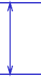
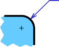
Leave a visible gap (≈ 1 mm) from a view and start drawing an extension line.
Extend the lines beyond the (last) dimension line 1-2 mm.
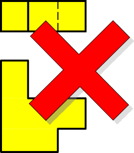
COMMON MISTAKE
Visible gap

Do not break the lines as they cross object lines.
COMMON MISTAKE
Continuous
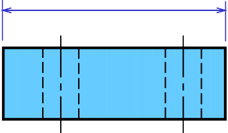
Dimension lines should not be spaced too close to each other and to the view.
COMMON MISTAKE
The height of figures is suggested to be 2.5~3 mm.
Place the numbers at about 1 mm above dimension line and between extension lines. c

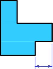
When there is not enough space for figure or arrows, put it outside either of the extension lines.
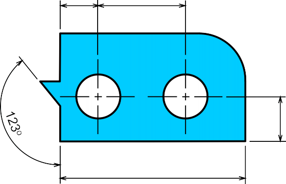
Angular dimension in degree with a symbol “o” place behind the figures (and if necessary minutes and seconds may be used together).
Length dimension in millimeters without
specifying a unit symbol “mm”.
The JIS and ISO standards adopt the unit of
The dimension figures are placed so that they are readable from the bottom and right side of the drawing.
-
Aligned method
The dimension figures are placed so that they can be read from the bottom of the drawing
- Unidirectional method


Place the notes near to the feature which they apply, and should be placed outside the view.
Always try to read horizontally.
10 Drill
LOCAL NOTES

COMMON MISTAKE
10 Drill
Too far

10 Drill
≈ 10mm
 Dimensioning Practices
THE BASIC CONCEPT
Dimensioning is accomplished by adding size and location information necessary to manufacture the object.
Clear Complete
Facilitate the
- manufacturing method
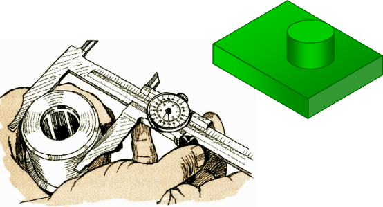
- measurement method
This information have to be
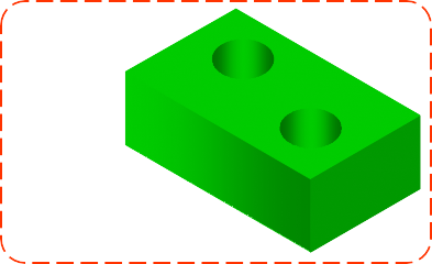
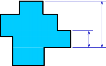
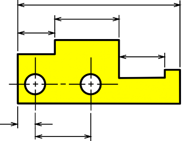
To manufacture this part we need to know…
-
Width, depth and
thickness of the part.
-
Diameter and depth
of the hole.
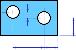
- Location of the holes
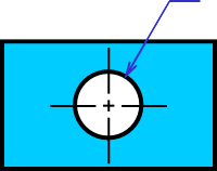
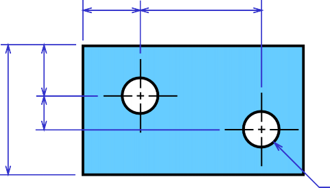
“S” denotes size dimension.
“L” denotes location dimension.
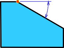
To dimension an angle use circular dimension line having the center at the vertex of the angle.
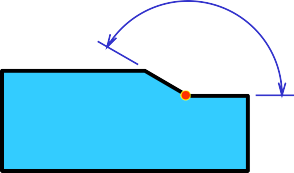
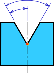

COMMON MISTAKE
ANGLE
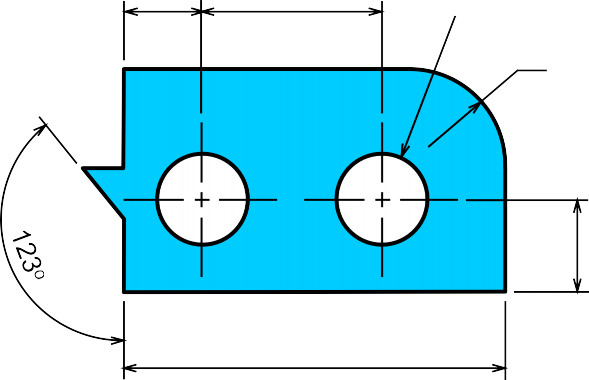
Arcs are dimensioned by giving the radius, in the views in which their true shapes appear.
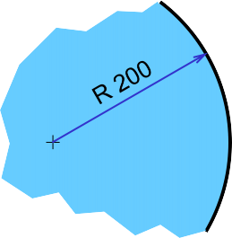
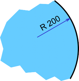
The letter “R” is always lettered before the figures to emphasize that this dimension is radius of an arc.
orfor
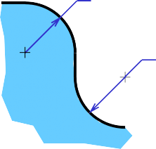
The dimension figure and the arrowhead should be inside the arc, where there is sufficient space.

Move figure outside
R 62.5
R 58.5
R 6.5


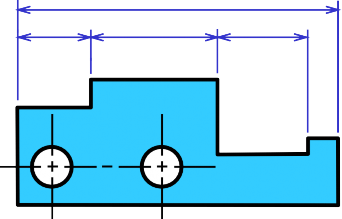
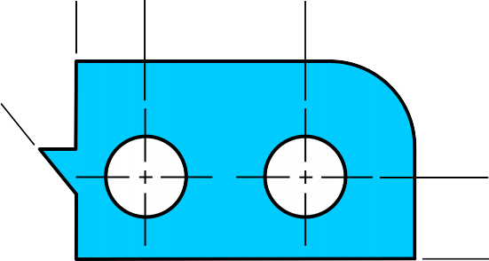
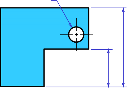
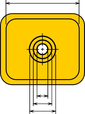
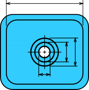
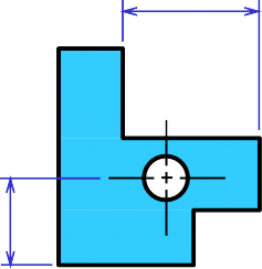
Size dimensions are diameter and depth. Location dimension must be located from its center lines and should be given in circular view.
Placement of Dimensions
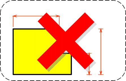
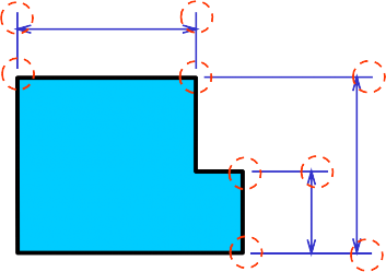
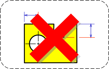
1. Extension lines, leader lines should not cross dimension lines.
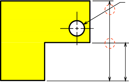
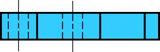
3. Extension lines of internal feature can cross visible lines without leaving a gap at the intersection point.
WRONG CORRECT

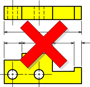
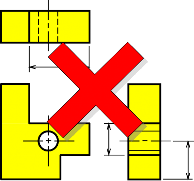
4. Do not use object line, center line, and dimension line as an extension lines.
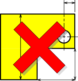
5. Avoid dimensioning hidden lines.

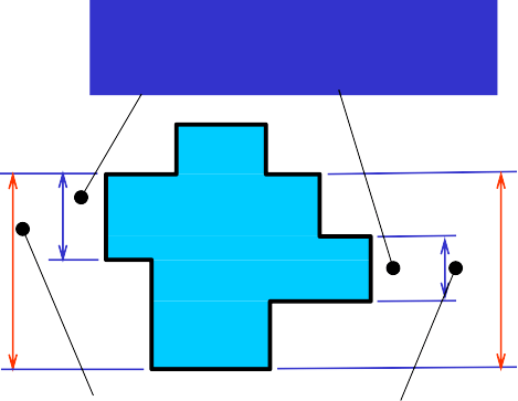
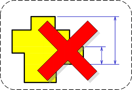
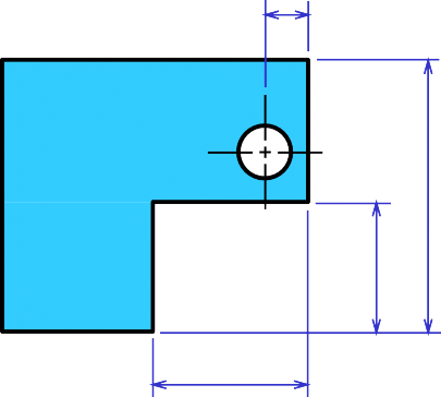
6. Place dimensions outside the view, unless placing them inside improve the clarity.
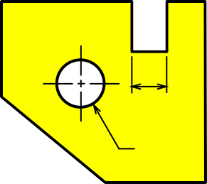
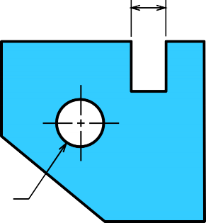
6. Place dimensions outside the view, unless placing them inside improve the clarity.
JUST OK !!! BETTER
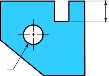
7. Apply the dimension to the view that clearly show the shape or features of an object.


8. Dimension lines should be lined up and grouped together as much as possible.

9. Do not repeat a dimension.