Section Views

TOPICS
Introduction
Terminology & common practices
Kind of sections
Introduction

ojection (convention
GRAPHICS COMMUNICATION WITH ENGINEERING DRAWING
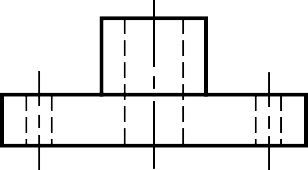
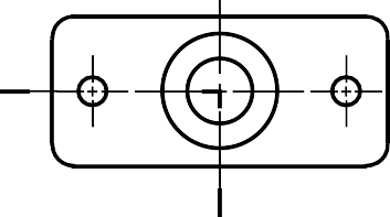
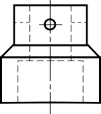
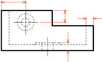
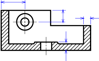
PURPOSES OF SECTION VIEWS
Clarify the views by
- reducing or eliminating the hidden lines.
- revealing the cross sectional‘s shape.
Facilitate the dimensioning.

EXAMPLE : Advantage of using a section view.
Terminology and common practices
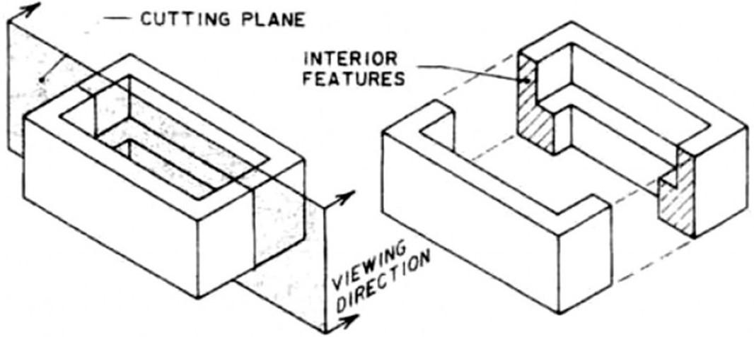
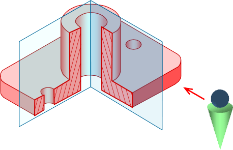
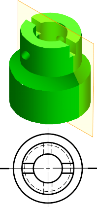
CUTTING PLANE
Cutting plane is a plane that imaginarily cuts
the object to reveal the internal features.
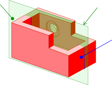
Cutting plane
Cutting plane line
Section lines
Cutting plane line is an edge view of the cutting plane.
CUTTING PLANE LINE

Indicate the path

T.L (optional)
of cutting plane.

CUTTING PLANE LINESTYLES
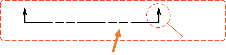
Thick line
Viewing
direction
This course will use

Thin linestandard
Viewing direction
SECTION LINING
Section lines or cross-hatch lines are used to indicate the surfaces that are cut by the cutting plane.
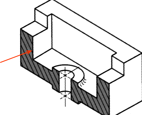
Section lines
Drawn with 4H pencil.
The section lines are different for each of material‘s type.
For practical purpose, the cast iron symbol is used most often for any materials.

Cast iron, Malleable iron

OPEN BOOK PAGE NO.84
Steel Concrete Sand Wood
COMMON MISTAKE

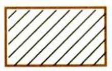
The spaces between lines may vary from 1.5mm(1/16″)
for small sections to 3mm(1/8″) for large sections.

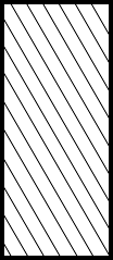
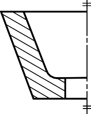
COMMON MISTAKE
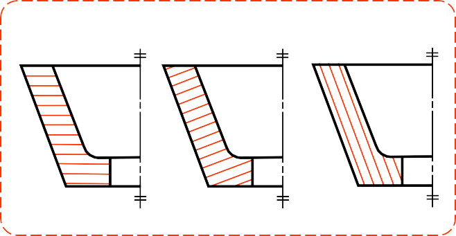
It should not be drawn parallel or perpendicular
to contour of the view.
Kinds of Sections
KIND OF SECTIONS
- Full section
- Offset section
- Half section
- Broken-out section
- Revolved section (aligned section)
- Removed section (detailed section)
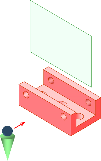
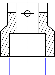
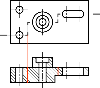
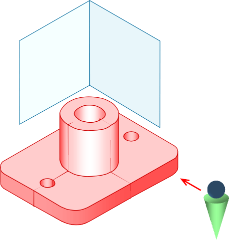
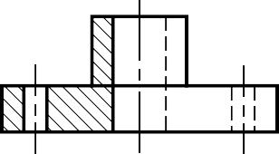
The view is made by passing the straight cutting plane completely through the part.
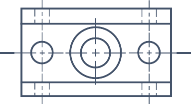
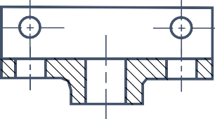
FULL SECTION VIEW

OFFSET SECTION VIEW
The view is made by passing the bended cutting plane completely through the part.

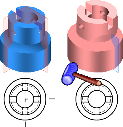
TREATMENT OF HIDDEN LINES
Hidden lines are normally omitted from section views.

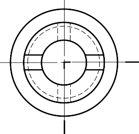
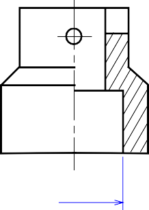
HALF SECTION VIEW
The view is made by passing the cutting plane halfway
through an object and remove a quarter of it.
A center line is used to separate the sectioned half from the unsectioned half of the view.
Hidden line is omitted in unsection half of the view.
HALF SECTION VIEW
The view is made by passing the cutting plane normal to the viewing direction and removing the portion of an object in front of it.
A break line is used to separate the sectioned portion from the unsectioned portion of the view.
Break line is a thin continuous line (4H) and is drawn freehand.
There is no cutting plane line.


EXAMPLE : Comparison among several section techniques

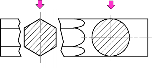
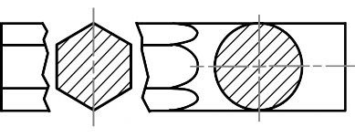
Revolved sections show cross-sectional features of a part.
No need for additional orthographic views.
This section is especially helpful when a cross-section varies.
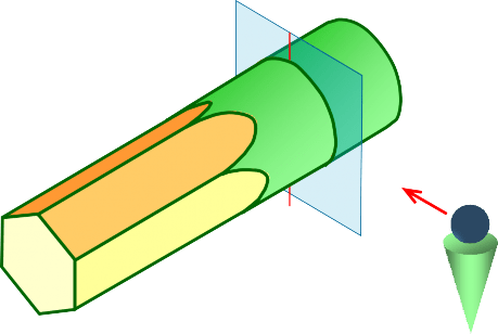
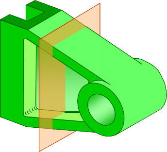
Basic concept


Basic concept

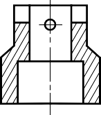
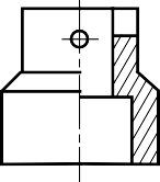
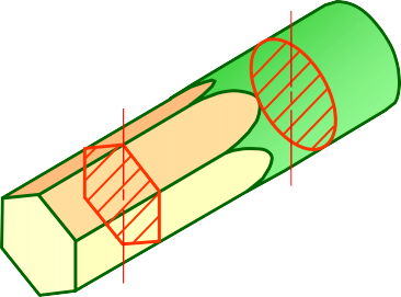
REVOLVED SECTION VIEW
Steps in construction
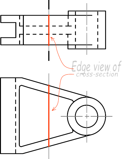
Edge view of
cross-section
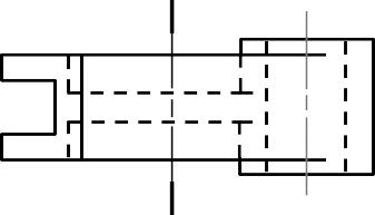
Step 1
- Assign position of cutting plane.
- Draw axis of rotation in front view.
Given

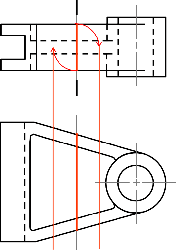
Step 2
a. Transfer the depth dimension to the front view.

Given
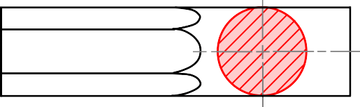
Step 3
- Draw the revolved section.
-
Add section lines.

FINAL PICTURE


Given
Placement of revolved section
-
Superimposed to orthographic view.
- Break from orthographic view.
-
Break Superimposed
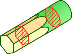
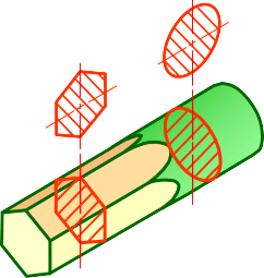
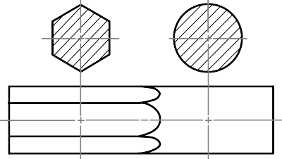
Removed section is revolved section.
Section view is shown outside the view.
Used where space does not enough for revolved section
Can be located elsewhere on a drawing with properly labeled
Revolved section
Removed section
Poor Preferred

Too messy !!


SECTION B – B
SECTION A – A
Dimensioning in Section View
In most cases, dimensioning of the section views follows the typical rules of dimensioning.
POOR GOOD

For a half-section view, use dimension line with only one arrowhead that points to the position inside the sectioned portion.