


TOPICS
Introduction Detail drawing
Assembly drawing
Introduction
Working drawing is a set of drawing used during the work of making a product.
DEFINITION
 Detail drawing
Working drawing
Assembly drawing is a drawing of various parts of a machine or structure assembled in their relative working positions.
Detail drawing is a multiview representation gof a single part with dimensions and notes.
DEFINITION
Detail drawing conveys the information
and instructions for manufacturing the part.
PURPOSE
Assembly drawing conveys
- completed shape of the product.
- overall dimensions.
- relative position of each part.
- functional relationship among various components.
Detail Drawing
2.2 Size description
2.1 Shape description
Object’s views
INFORMATION IN DETAIL DRAWING
1. General information
Title block
2. Part’ s information
2.3 Specifications
Notes
GENERAL INFORMATION
- Name of company
- Title of drawing (usually part’s name)
- Drawing sheet number
- Name of drafter, checker
- Relevant dates of action (drawn, checked, approved etc.)
- Revision table
- Unit
- Scale
- Method of projection
PART’ S INFORMATION
Shape
Size
Specifications
- Orthographic drawing
- Pictorial drawing
- Dimensions and Tolerances
- Part number, name, number required
- Type of material used
- General notes
- Surface finish
- General tolerances RECOMMENDED PRACTICE
draw all parts using the same scale.
Otherwise, the scale should be clearly note under each part’s drawing.
PLACING AN INFORMATION
(This course)
Completed dimension orthographic drawing
Part No., Part name, material, Number required
Notes
Unit, fillets & rounds sizes etc.
Title block
EXAMPLE : Interpreting detail drawing
Revision table
Assembly Drawing
TYPES OF ASSEMBLY DRAWING
-
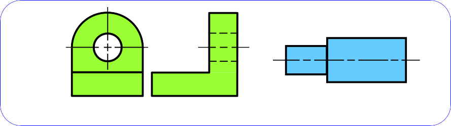
Exploded assembly drawings
The parts are separately display, but they are aligned according to their assembly positions and sequences.
-
General assembly drawings.
All parts are drawn in their working position.
- EXPLODED ASSEMBLY
- EXPLODED ASSEMBLY
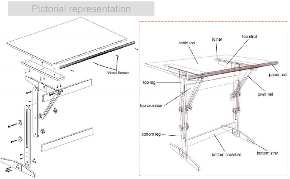
Pictorial representation
Finished product
-
EXPLODED ASSEMBLY
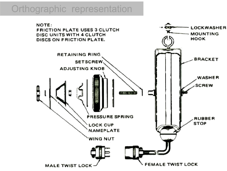
Orthographic representation
Pictorial
Orthographic
- GENERAL ASSEMBLY
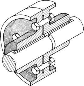
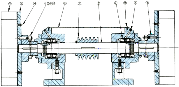
Only dimensions relate to
machine’s operation are given in tabulated form (not shown).

Only dimensions relate to machine’s operation are given.
2. GENERAL ASSEMBLY
Locate above or beside the title block. Fill the table from the bottom.
PART LIST (BOM)
|
3 |
SET SCREW |
1 |
Stainless Steel,
M3 HEX SOCK CUP PT |
|
2 |
SHAFT |
1 |
Stainless Steel |
|
1 |
SUPPORT |
2 |
Cast Iron |
|
NO. |
PART NAME |
REQD. |
MATL. & NOTE |
EXAMPLE : Selection of a necessary view
Student A Student B
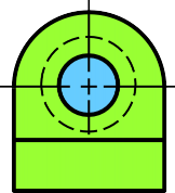
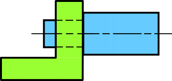
Which is an appropriate view for assembly drawing ?
Hidden lines usually omit unless they are absolutely necessary to illustrate some important feature that the reader might otherwise miss.
GENERAL PRACTICE POINTS TO CONSIDER
- Surface finishing
- Tolerance
– Size
– Geometry
SURFACE FINISHING
Surface finishing means the quality of a surface. It relates to the level of roughness of a surface.
Purpose
- To control the accuracy in positioning and tightness between mating parts.
- To reduce the friction, especially for the part moves relative to other parts.
Tolerance is the total amount dimension may vary.
TOLERANCE
It is defined as the difference between the upper and lower limits.
Purpose
- To control an interchangeability of parts.
- To ensures the mating part will have a desired fit.


