
EARTHQUAKE RESISTANT BUILDINGS Standardized cross-sections of reinforced concrete elements
Standardized cross-sections of reinforced concrete elements
Modern times require the use of standardized shapes and sizes of columns and beams com- posing the load bearing frame of structures. This means regular usage of elements with sec- tions that belong to certain categories. Of course the use of elements with non-standardized sections is not prohibited but it should be made only in certain occasions. When building a structure, the largest the standardization is, the highest is the provided quality level and the lower is the resulting construction cost.
Standardization serves in:
- the reduction of construction cost since standard moulds and stirrups are more economical,
- the increase of construction quality as usage of standardized formworks and reinforcement helps in maintaining a standard high quality level,
- the familiarization of architects with typical static rules applied to structural members,
- the designers accumulating experience concerning the formation and behavior of construction,
- the faster and problem-free construction and supervision of the structural frame,
- the automatic optimization of the structural frame with the use of PC software.
It is highlighted that the shape and size standardization should not restrict the variety of sections available to the designer. However the latter should make use of it only when it is necessary.
At present there is no official standardization, but based on the regular practices and the typical antiseismic requirements the following format is proposed:
COLUMNS
- Rectangular
25303540455060751001502002525x4025x5025x7525x10025x15025x2003030x3030x4030x5030x6030x7530x10030x15030x2003535x354040x4040x6040x754545x455050x5050x756060x607575x75
Notes:
The 45×25 column is highly standardized only as far as the stirrups are concerned, because it is commonly used as integrated column to the ends of both shear walls and composite elements.
-
When using industrial formworks, it is recommended to avoid usage of 40×40 columns. Moreover, it is preferred to use shear walls with length equal to 105cm instead of 100cm and 195cm or 210cm instead of 200cm.
- Circular
|
D |
30 |
35 |
40 |
45 |
50 |
60 |
75 |
100 |
- “Γ” isosceles
|
b/d |
25 |
30 |
35 |
40 |
50 |
60 |
75 |
100 |
150 |
200 |
|
25 |
25×45 |
25×75 |
25×100 |
25×150 |
25×200 |
|||||
|
30 |
30×45 |
30×75 |
30×100 |
30×150 |
30×200 |
-
Elevator
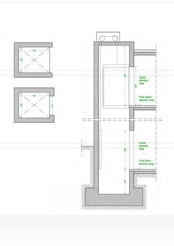
According to the specifications issued by the Ministry of Industry, the minimum clear openings in the elevator shaft are:
For common multi-storey residential buildings:
for mechanical movement 1.40 x 1.70 (m)
for hydraulic movement 1.35 x 1.85 ή 1.55 x 1.65 (m)
For buildings with height up to 9.0m:
for 3 persons 1.10 x 1.35 (m)
for 5 persons 1.20 x 1.50 (m)
The opening width of the elevator door must be equal to 1.05m (building width) and the lintel must be placed 2.20m above the final floor level. This specific width is necessary in order to provide sufficient space to enable a wheelchair user to pass unobstructed through the door even after the jamb has been placed. In multi-storey residential buildings, it is compulsory to construct elevator doors with that width however, its construction is recommended to every other building.
The clear height of the elevator shaft must be at least 3.40m, calculated from the final level of the upper storey.
The clear depth of the elevator shaft must be at least 1.40m, calculated from the final level of the first stop
In order to avoid fatal imperfections especially in the maintenance of the multi-storey structure’s verticality, it is highly recommended to construct the internal space with dimensions at least 5cm larger than the minimum required. If there are concrete door posts, the elevator door must have a clear opening equal to 1.10 m. Usually elevators have a “Π” shape without door posts, either due to technical reasons or because a sliding elevator door is required. The typical width of the elevator elements (shear walls and door posts) is around 25 ή 30 cm.
In all cases, the required dimensions should be verified by the person responsible for the eleva- tor installation.
Minimum clear dimensions of an elevator in a typical multi-storey residential building
BEAMS
|
b/d |
25 |
30 |
35 |
40 |
45 |
50 |
60 |
75 |
100 |
125 |
150 |
200 |
|
20 |
||||||||||||
|
25 |
25×40 |
25×50 |
25×60 |
|||||||||
|
30 |
30×40 |
30×50 |
30×60 |
|||||||||
|
40 |
40×50 |
40×60 |
40×75 |
|||||||||
|
50 |
50×50 |
50×60 |
50×75 |
Notes:
-
Sections with width lesser or equal than 30cm, apply to relatively small structures with usual strength requirements.
-
When thermal insulation is embedded inside the formwork, the only practical way to standardize this procedure is to use boards with 5cm thickness since industrial moulds and stirrups usually have dimensions divided by 5.
FOUNDATION CONNECTING BEAMS
|
b/d |
35 |
40 |
45 |
50 |
60 |
80 |
100 |
120 |
150 |
|
30 |
30×80 |
||||||||
|
40 |
40×80 |
40×100 |
40×125 |
||||||
|
50 |
50×100 |
40×125 |
50×150 |


