
Reinforcement in structural elements
Columns
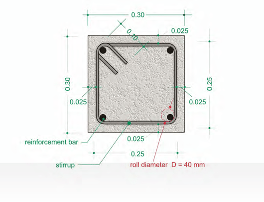
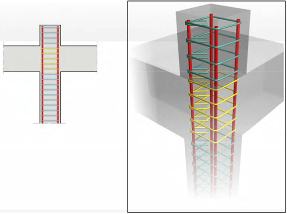
Consider a column with cross section 30x30cm. This is the smallest allowable column section when seismic behavior is required. It is reinforced with 4 longitudinal bars and one stirrup. The cross section described is not generally used but it was chosen in this introductory paragraph for training purposes.
The column has a length of 2.70m while the length of the above joint is 0.50m (equal to the height of the concurrent beam). The transverse reinforcement is a usual stirrup with a Φ10 di- ameter. The longitudinal reinforcement is comprised of 4 Φ20 bars. The stirrup’s cover depth is 2.50cm. The shear reinforcement can be referred to with various names such as stirrups, ties, hoop reinforcement etc.
Columns are the most critical structural components to ensure the required seismic perform- ance of the building and the shear reinforcement is the most critical component of the columns. In every column we define areas with high ductility demand (when earthquake loads are ap- plied) which they are called critical, areas with lower ductility demand, called non-critical and the joint area (i.e. the common area between the column and the concurrent beam).
COLUMN 30 x 30cm (with critical and non-critical areas)
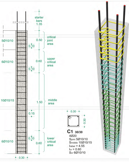
In the first case, Φ10 stirrups, at a spacing of 15cm, have been placed throughout the entire non critical area of the column. That area’s length is 1.50m and therefore the number of the provided stirrups is 10. This is presented as 10Φ10/15.
The stirrups placed in each of the column’s critical areas are Φ10/10, their total number is 6 and consequently they are presented as 6Φ10/10.
The stirrups placed in the joint area are Φ10/10, their total number is 5 and therefore they are presented as 5Φ10/10.
The label of the column’s reinforcement detail provides guidance for the proper placement of the rebars.
COLUMN 30 x 30cm (with its entire length taken as a critical area)
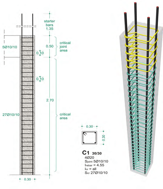
In the second case the entire length of the column is regarded as a critical area and Φ10 stir- rups have been placed at a spacing of 10cm. The column’s length is 2.70m therefore, the pro- vided stirrups are 27. This is presented as 27Φ10/10.
The stirrups placed in the joint area are Φ10/10, their total number is 5 and consequently, they are presented as 5Φ10/10.
Note
The hooks of the shear reinforcement should be formed in different positions along the perime- ter of the stirrups in each layer but due to the frequent use of industrial stirrup cages this is not feasible.
Lap-splices in columns
In multi-storey buildings it would be ideal if each of the column’s longitudinal rebars could be placed as one single piece throughout the structure’s entire height. This however cannot be accomplished for practical reasons therefore, the length of the longitu- dinal rebars is equal to the height of each storey.
When lapping steel bars from successive stories, it is important to ensure the correct transmission of forces from the rebars of the subjacent floor to the rebars of the superjacent floor. This can be achieved by weld- ing, however this method has a number of technical difficulties and it is used only in special occasions. The practice usually followed is the rebar lap-splicing
-
rebar lapping by means of contact.
 The length of the placed bars must be extended by an additional length called ‘lap length’, which has to be equal or greater than the length required for the lapping of corresponding rebars between two suc- cessive storeys. This length is equal to the rebar’s diameter multiplied by the ‘contact coefficient’ (its val- ue varies from 40 to 70).
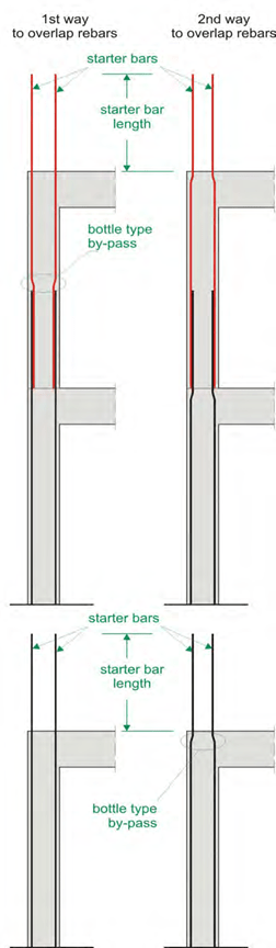
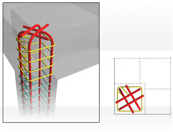
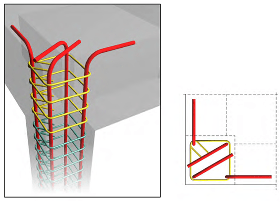
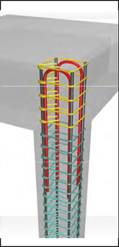
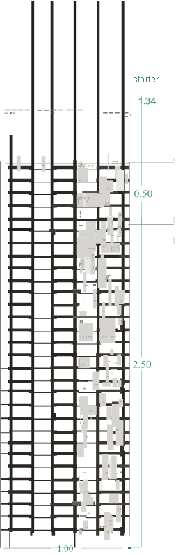
It is important to thoroughly understand how the lap- splices are being done in practice. One must always keep in mind that in order for the stirrups to provide confinement, every rebar must be placed inside one of their corners. This however is difficult to be done at the beginning and at the end of the lap-splice and it can be achieved only with special practices. In case the rebars are wired together on the site, the lap- splice is mandatory to be done according to the first way shown at the opposite figure.
The starter bars of the subjacent storey must be kept straight while the rebars of the above floor must be bent at their joint point. The bent part must extend to one or two stirrups. The use of rebars with diameters greater than Φ20 or Φ25 makes bending in situ ex- tremely difficult if not practically impossible, that is why the rebars have to be bent prior to their place- ment with the use of a bending machine.
Note:
The ‘contact coefficient’ is proportional to the steel’s yielding strength and reverse proportional to the concrete’s compressive strength 1.
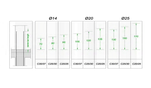
The following table shows the necessary lap lengths in cm, for three different rebar diameters in combination with three different concrete grades
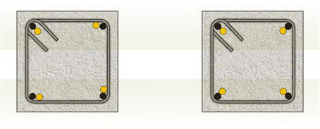
The bent rebars can be placed in contact with the straight ones in any direction as shown at the following figures.
In case there are no seismic design requirements and for serviceability reasons, it is preferred to place more bars with smaller diameter around the perimeter instead of fewer bars with larger diameter. When seismic design is required, as it is for the columns referred in this book, it is preferred to place rebars only inside the corners of the stirrups thus ensuring that no buckling will occur. Therefore, it is better to use fewer bars with larger diameter. Moreover, structures designed to withstand the seismic hazard, have a considerable amount of steel reinforcement in their joint areas so the small number of column rebars enables the proper reinforcement.
1 For steel class B500 and concrete grade C20/25, the contact coefficient is in the order of 67, for concrete grade C25/30 the contact coefficient is in the order of 58, and for concrete grade C30/37 the contact coefficient is in the order of 51.
In a square 40x40cm section with the stirrups placed in a rhombic layout (having 4+4 corners), 30cm2 total area of required reinforcing steel and use of longitudinal rebars up to Φ20, the usual reinforcement is 4Φ20+12Φ142. If using longitudinal rebars up to Φ25 the ideal choice is 4Φ25+4Φ203.
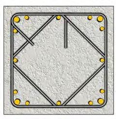
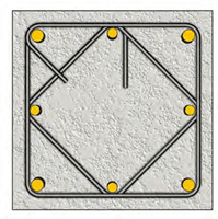
reinforcement comprised by 16 bars, 4Φ20+12Φ14
equivalent reinforcement comprised by 8 bars,
4Φ25+4Φ20
The use of longitudinal rebars with diameter greater than Φ20 is allowed only if the following conditions are met:
- Use of high-strength concrete mixture, so as to lessen the required lap lengths.
- Mandatory use of bending machine for the bending of the longitudinal rebars (in the lap- splice areas) and of course, an accurate detailing with the exact rebar dimensions.
- Use of crane as a single Φ25 rebar with 4.65m length weights around 18 Kg.
The first condition regards the concrete industry while the second and third regard the formation and placement of the reinforcing steel. The latter two conditions are discussed further below.
High-strength concrete mixtures like C25/30 or C30/37 should be given no consideration as:
- they are produced by most cement industries.
-
although they have a relatively higher cost compared to the regular concrete mixtures, their use allows for a smaller amount of reinforcing steel.
-
they have a high cementius content thus ensuring a longer structural frame’s service life. This is crucial in cases where the buildings are in adverse environment such as being at a distance<1 Km from the sea.
2 From table 1 derives that 4Φ20+12Φ14 correspond to 4*3.14+12*1.54=12.56+18.48=31.04cm².
3 From the same table derives that 4Φ25+4Φ20 correspond to 4*4,91+4*3.14=19.64+12.56=32.20cm²
In most countries of the world with an advanced construction industry, concrete grades higher than C25/30 and C30/37 are being used even in the common structures.
The construction industrialization together with the development of the reinforcement implemen- tation, lead growingly not only to the use of prefabricated stirrup cages but also to the use of prefabricated columns that are positioned with the use of a crane.
The prefabricated reinforcement and its mechanical implementation are two simultane- ously developing techniques.
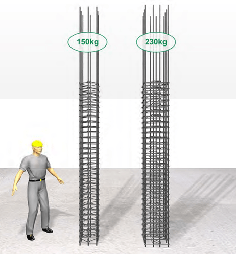
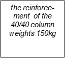
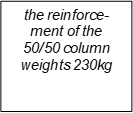
The earthquake resistant columns have a large mass. For instance, the smallest allowable col- umn mentioned before (stirrups and longitudinal reinforcement), has a mass equal to 60kg as opposed to the usual antisesimic columns whose mass is much greater. A common 40/40 col- umn with Φ10/10 stirrups placed in a rhombic layout and 8Φ20 longitudinal reinforcement, weights 150kg and the also usual 50/50 column, with stirrups placed in a cross layout and 12Φ20 longitudinal reinforcement, weights 230kg.
Anchoring the reinforcement of the upper floor level
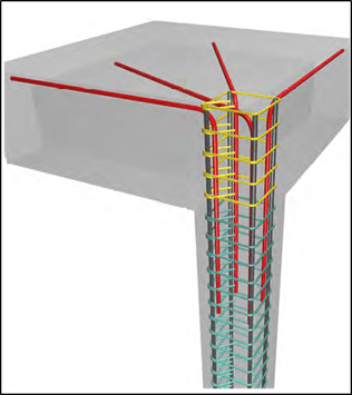
Column rebars must be properly anchored to the upper floor level in order to behave in the re- quired way.
The most effective way to anchor the upper floor column rebars is by creating a “concrete hat” on the top of the column thus allowing the rebars to be anchored without being bent.
Anchoring the upper column rebars with the use of an additional ‘concrete hat’ upon the flat roof is a simple and neat solution.
If the construction of a ‘column hat’ is not a desirable solution due to reasons like e.g. the need for a flat roof, then the column rebars of the upper floor can be anchored according to one of the following ways:
- hooks bent at 180°

- hooks bend at 90° (A case)
- hooks bend at 90°(B case)
- use of extra hairpin reinforcement bent at 90° or 180°
- When placing small bar diameters inside high-strength concrete mixtures, the straight an- chorage length might be short enough to fit inside the joint area.
Reduction of the column’s section size along its length
The reduction of the column’s size from one storey to the other is not favorable either from a theoretical or from a practical point of view. Especially in columns where earthquake resistant behavior is required it must be avoided. However, there are cases where the subjacent column is larger than is the superjacent column.
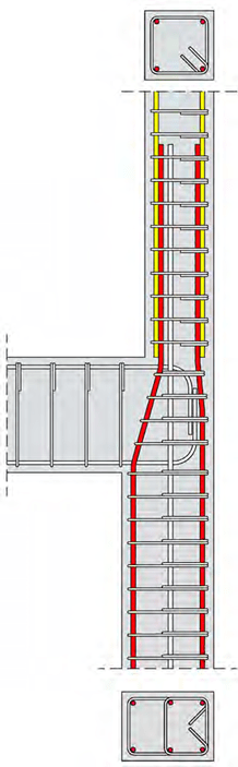
Reduction of the section’s size along the height by bending rebars into the shape of a bottle
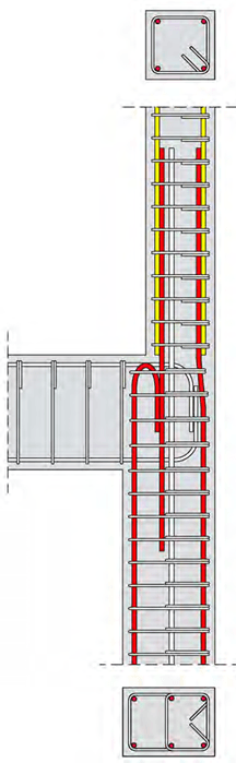
Reduction of the section’s size along the height by terminating some of the old rebars and im- planting new ones
The reduction of the column’s size between two successive storeys creates two basic problems. The first regards the reinforcement layout that differs between the upper and the lower column and the second regards the difficulty in the anchorage of the lower column rebars that are placed outside the peripheral stirrups of the upper column.
The first problem is faced by fitting starter bars to the proper places at the upper part of the low- er column.
The second problem is faced with two different ways:
-
By ending the rebars that are placed outside the peripheral stirrups of the upper column and
- By bending the lower column rebars, into the shape of a bottle, and anchoring them inside the upper column.
This work, either done by the first or by the second way, must be done with extreme care be- cause the earthquake resistant column must have transverse reinforcement (stirrups) that will provide adequate confinement in the joint area. It is advised to form the stirrup hooks in different places between successive layers. It is reminded that this practice is necessary for the column’s strength even if the adjacent beams fail.
In order for the bent up rebars to be adequately confined in the interior part of the joint area, they have to be placed inside the corners of stirrups. This can be achieved by forming the stir- rups (by hand, on by one) with a decreasing section size.
The rebars of the lower column that continue to the upper column, is advised to be bend inside the joint area.
When ending the rebars placed outside the peripheral stirrups of the upper column, their an- chorage must be secured by one of the ways described in the previous paragraph.
The same rules apply to any case of reduced column size, e.g. in case of bilateral reduction of the column’s section size.
Reinforcement in typical columns
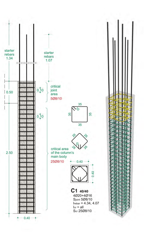
Column with section 40x40cm
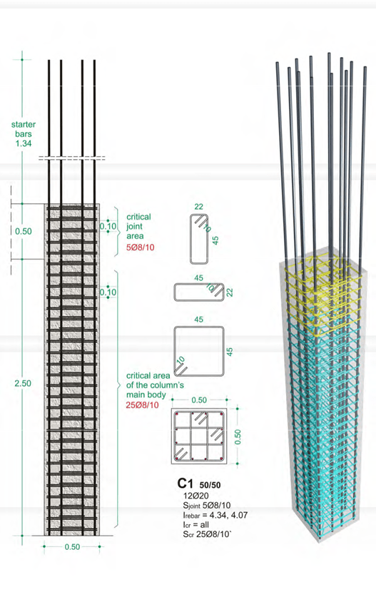
Column with section 50x50cm
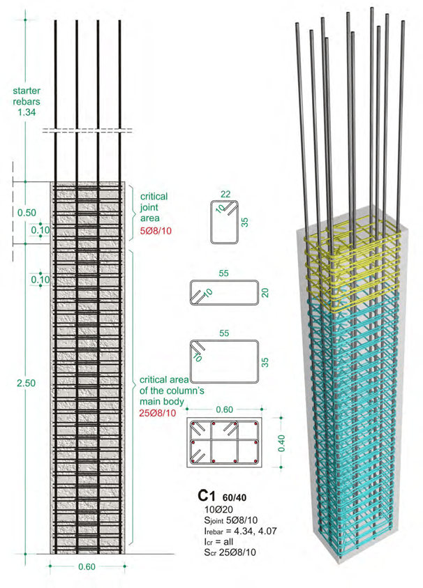
Column with section 60x40cm
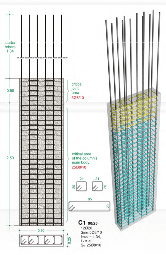
Column with section 90x25cm
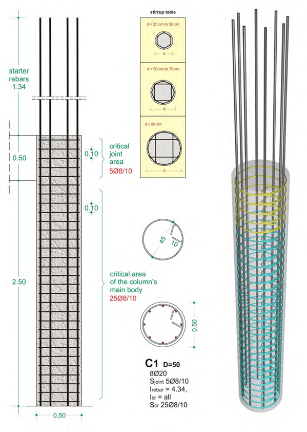
Column with a circular section D=50cm
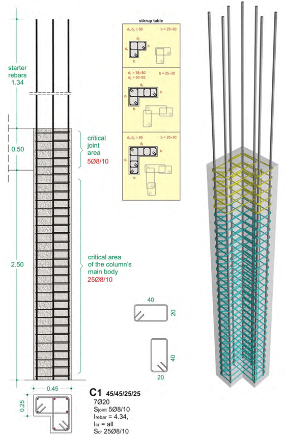
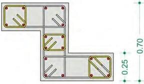
Column with ‘Γ’ section 45x45x25x25cm
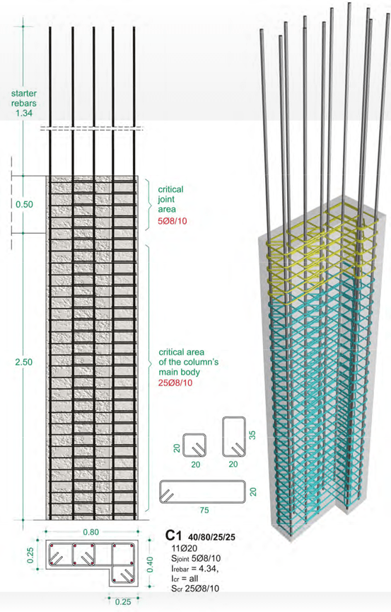
Column with ‘Γ’ section 40x80x25x25cm
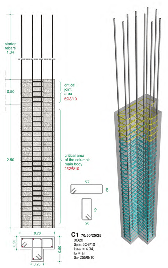
Column with ‘T’ section 70x50x25x25cm
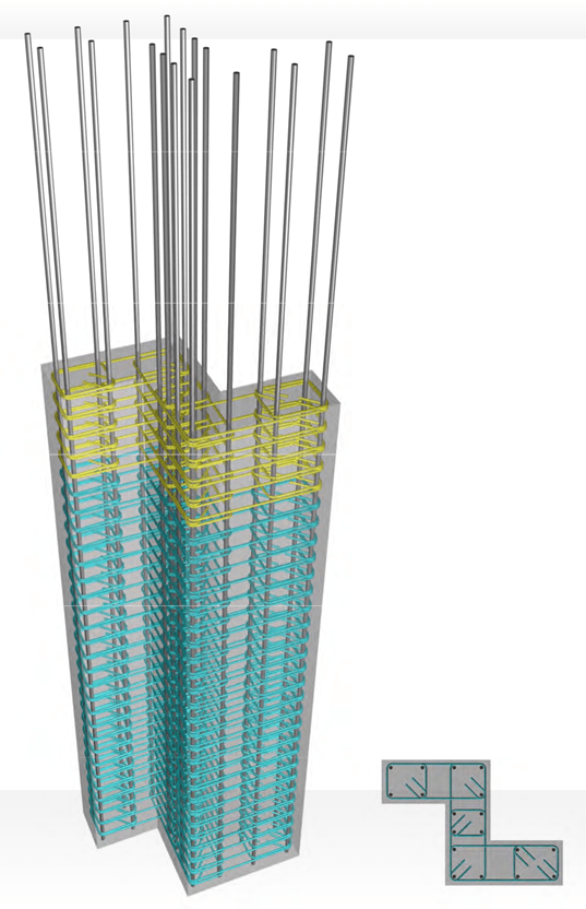
Column with ‘Z’ section 70x65x60x25x25x25cm


 20
20
[

60
 20
20


 critical ( joint
area
 508/10


 [ 0
[ 0
60
N
•
 •
•
ll)
N
c:)
 •
•
0.60 •
critical area of the column‘s
0 main body
N 2508/10
 20
20

 • 0.25 •
• 0.65 •
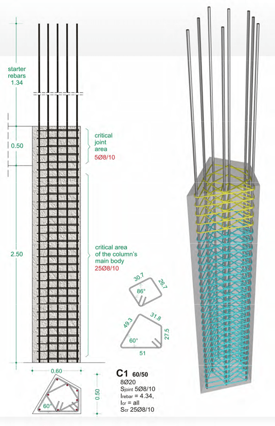
c1 40/80/25/25
11020
Sjoint 508/ 10
lrebar = 4.34,
lcr = all
Ser 2508/ 10
Column with quadrilateral section 60×50
Note:
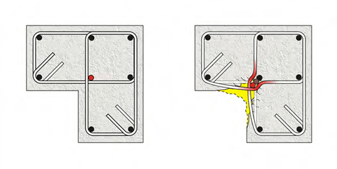
Placing a rebar in the internal corner of composite sections (‘Γ’, ‘Ζ’ section etc) is optional be- cause:
-
it does not significantly enhance the flexural strength since it is not placed in a section’s cor- ner (based on the fact that tensile stresses appear to the external corners of the elements’ sec- tions)
-
it does not increase the confinement because in case of an intense earthquake, where con- crete spalling will occur, that rebar might buckle since it is not completely restrained.
-
however, in all cases this corner rebar may be constructional used without though calculating its contribution to the section’s confinement.
The internal rebar (in red), in a severe seismic event, might buckle (due to the bulking of stirrups) and therefore it will not contribute to the confinement.


