
Cracked Slab Deflection Control
Before we run the analysis and design, there is an option in SAFE that allows the user to
define cracked slab deflection controls. Under the Analyze menu > Set Options, you will
see a Normal and Cracked Deflection button. When the Analysis Type is Normal and
Cracked Deflections, select the Interpolation Options for Slab Cracking Modifier (linear,
Quadratic, Cubic, or 4th order). Accept the default Maximum Mesh Dimension or enter a
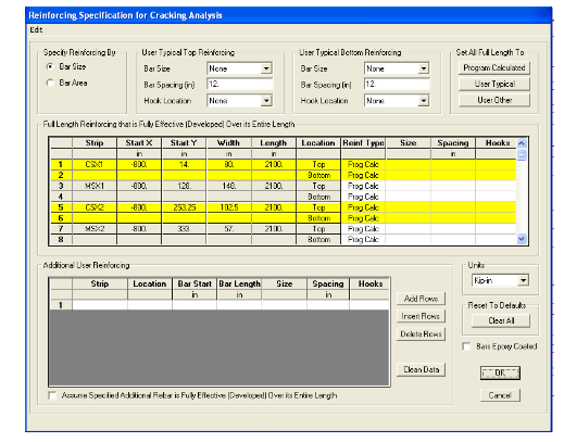
new value by typing in the edit box. The Reinforcing Specification for Cracking Analysis
form is used to specify the rebar to be used in the cracking analysis. Note that the
spreadsheet in the middle of the form displays a strip ID, the X and Y starting points for
the rebar, the width and length of the rebar, and the location (top or bottom) of the rebar.
The form has been designed to allow you to use the three options (Program Calculated,
User Typical and User Other) in conjunction with one another to quickly tailor data entry
to meet your specific needs. For example, if most, but not all, of the rebar can be
calculated by SAFE, (1) click the Program Calculated button; (2) click the cell in the
Reinf Type column for the row of data to be altered; (3) select the User Typical or User
Other option; and (4) provide additional data input as described above for the User
Typical or User Other options to modify those rebar that require specification other than
the default. See Figure 32:
Figure 32 Reinforcing for Cracking Analysis
We are now ready to run the analysis and design for the slab. To do this, go to Analyze >
Run Analysis. You will now see the deflected shape of the slab. To design the slab, go to
Design > Start Design. The X-Strip rebar is now shown on the screen. Refer to Figure 33:
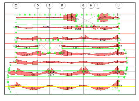
Figure 32 X-Strip Reinforcing
The model is in plan view showing the amount of steel required based upon the moment
calculated. Go to Design > Display Design Info and the Slab Reinforcing dialogue box
will appear. We are interested in viewing the Y-direction strip and determining the
amount #6 bars required for the middle strip. After making these selections, the Slab
Reinforcing dialogue box should look like Figure 33:
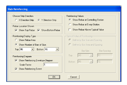
Figure 33 Slab Reinforcing Dialogue Box


