
TYPICAL FEATURES PRESENT IN A BUILDING
Window
When window is cut horizontally, as in plan of the building, an empty space is obtained
between two ends of the solid wall. Symbol of brickwork in section will come in the solid wall but not in the space for the window as in Fig. 6.10 (A). Further from behind the cutting plane, two ends of the sill (the wall at the bottom of the window) will be visible. Window is always shown in the closed position meaning that two lines representing the thickness of the window itself are to be drawn. These lines may be drawn anywhere in the thickness of the wall with any suitable spacing in-between, not according to the scale. These four lines will serve the purpose of a symbol for window in section. If sunshade is to be added on top of the window, as in external walls to protect the window from rain and sun, it must be shown by dashed line in plan because actually it is removed with the upper part of the building during the cutting assumed. Each type and size of the window is denoted by different numbers like W1, W2, W3, etc. Wherever same type of window (suppose W1) comes, only its type (W1) is written and then its dimensions may separately be given in the form of a standard table called Schedule of Openings. It will avoid duplication of dimensions and will provide a complete record of the number and size of all the doors, windows and ventilators. Sizes of the features of this type are always recorded in the following standard way:
W,V,D (Number in subscript) Horizontal dimension x Height
For example, in W2 6-O” x 4′-O , 6-O” will be the horizontal dimension and 4-0′ will be the height. Di 4′-O”x 7′-O” means a door having 4′-O” horizontal dimension and 7′-O” vertical dimension.
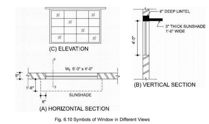
Window in vertical section is shown; by four lines as in the horizontal section, see Fig.
(8). On top of the window, there is R.C.C. lintel shown by light green shade.
Sunshade, if present, will be connected with the lintel shown by the same RC.C.
symbol. For elevation (or exterior view) of the window, as in Fig. 6.10 (c), the outer
line is drawn exactly according to the dimensions whereas the inner pattern is only
drawn symbolically without scale in main drawings of the buildings. The details of
doors, windows and ventilators may be provided in separate drawings.
Ventilator
Ventilator is denoted by the letter “V” and is shown in vertical section and elevation
just like a window. When we assume cutting for the plan, the ventilators are removed
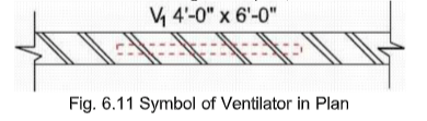
with the upper part. At the level of cutting, there is a solid wall shown by the symbol
of brickwork in section. Symbol of a ventilator, just like a window, is then
superimposed on the plan by using dashed lines. A window going near the ceiling is
called ceilacious window denoted by “CW”.
Door
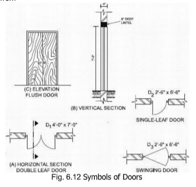
Door is denoted by the letter D and is shown in vertical section in closed position like
a window. At the bottom of the door, the top floor finish layer will be continuous
over the brick wall underneath. D.P.C. is not provided under the doors and all such
openings which start from the floor level like verandah opening, etc. In plan, the door
is shown in open position and, with a thin line, swing of the door during opening is
also shown. The space between two ends of the solid wall is left exactly according to the dimensions of the door. Frame of the door is then drawn symbolically without the
actual dimensions. Next, for a double leaf door, considering the inner edges of the
frame as the centers, two arcs are drawn having radii equal to one-half the clear distance between both ends of the frame. Thick lines showing the leaves of the door are then drawn perpendicular to the wall. The advantage of this symbol is that it also indicates the space consumed by the door during opening. Double-leaf door- is preferred for wide doors and for the doors present away from the corners of the rooms. Single-leaf door should preferably be accommodated near the corner of the building leaving a gap
of about 4 1/2″ from
6.4.4. D.PP..C
Damp proof course (DPC) is provided inside all walls which are continuous above the
plinth level. Its top is generally made in level with the top of the floor. Its thickness
varies form 1 1/2″ for residential buildings in ordinary soils to 3″ for official
constructions. The symbol of DPC in section is a dark black shade as shown in Fig.
6.13.

Typical Foundation Details for a 9″ Thick Wall
The details for a typical foundation for 9″ thick wall are shown in Fig. 6.13. It is
preferable and time saving to draw a construction line first (serving as the center-line of the wall) and then to measure half distances from this line on both the sides. If this procedure is followed, the difference of measurement in different steps will not accumulate.
Roof Details
Although there are many variations in the roof details depending upon type of the
building, the typical details are produced in Fig. 6.14. At the top 1 1/2″ thick layer of brick tiles is shown having brickwork symbol. Below this a single 4″ thick layer is shown for both the mud plaster and the earth filling. Polythene sheet and bitumen coating have much lesser thickness and cannot be shown on an architectural scale; generally a thick line is drawn for these two layers. At the bottom, R.C.C. roof slab is shown by light green shade. A thick vertical line is then drawn upwards and a pointer is marked at a height so that all the roof details may be written within the space available between this pointer and the roof- top.
Next, suitable guide lines for the lettering are drawn and each layer is described in a separate line ending with the word over1 starting from the top-most layer, as shown in the figure Description of a layer includes its thickness and an about its material of construction.

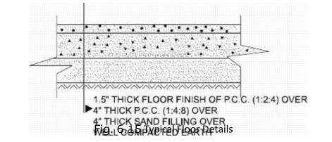
Floor Details
Floor details are written in the same way as the roof details. Each layer is described in separate line and the description is started from the topmost layer. Compacted earth at the bottom of the ground floor has no definite thickness as the earth is continuous below.
Fig. 6.15 Typical Floor Details


