
DRAWING OF A BUILDING
After having practice to draw plan, section and elevation for important features of a
building, drawing of a small typical building may be started. A single room building may
serve the purpose of a shop, clinic, cafeteria or a filling station office, etc. Two- room
building may serve the purpose of a bus-stop, clinic, or post-office. Here a two room
building with a verandah is considered in detail which may be recommended for a small
primary village school, an octroi post, or for a check post.
The building shown in Fig.6.16 consists of two rooms of equal size with a verandah on
the front side in an open area. The ceiling height for verandah is lesser as
compared with the rooms and its roof is supported over a beam present on all the
three open sides. The beam in turn is supported over three columns and corners of the
rooms. Floor is provided at some height from the G.L. and there are two steps which
lead into the building. Note that risers are three while the treads are two as discussed
in paragraph 6.1.17. From within the open spaces of the verandah, two doors and
two windows are visible. These doors lead into two rooms having one window each
within the back wall and one window each near the doors. There are two almirahs
present in the common wall one opening into the left room while the other into the
right room.
If such a building is cut by a horizontal cutting plane 6-in higher than the S.L. and the
upper part is removed, we get part of the building as shown in Fig. 6.17. This figure is the three-dimensional representation of the building after cutting with the arrow showing the entrance. The orthographic view of the same part, called plan, is shown in Fig. 6.18.
The view is to be completely dimensioned. The dashed line present between columns
of the verandah show the inner edge of the beam above. The outer edge of the
beam is not shown by dashed line because full line is already there showing edge of
the floor. While writing size of a room, its inner horizontal dimension parallel to
the front of the building is always written first, then the other inner horizontal
dimension is written with a “X” in-between. A 15′-0’x 12′-0′ room means that 15-0″
dimension is parallel to the front side of the building.
Fig. 8.19 is a repetition of Fig. 6.17 but in it the path of cutting to obtain section is also
shown by shading (cutting plane denoted by AA). This cutting is for whole of the building starting from the top of the parapet right up to the bottom of the foundations. After assuming this cut if we remove the left part of the building, the remaining portion will look like Fig. 6.20. This cutting exposes nearly all the details like roof layers, floor layers, lintels, sunshades, beams, thicknesses of walls, ceiling
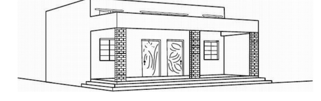
Fig. 6.16 Perspective View of a Building With Two Rooms and a Verandah
heights, heiqhts of doors and windows, and foundations etc. That is why section is the
most important view in the Building Drawing. The three dimensional view of the Fig 6.20 provides an idea of the sectional view from one side whereas, it may also be used to have an idea about the
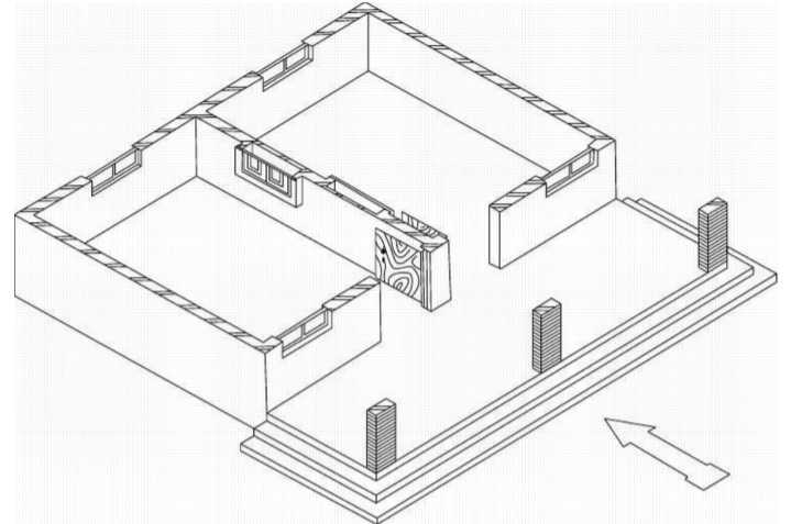
Fig. 6.17 Isometric View of the Building After Cutting for Plan
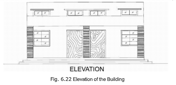
elevation when looked from the other side. Interrelationship of various features shown
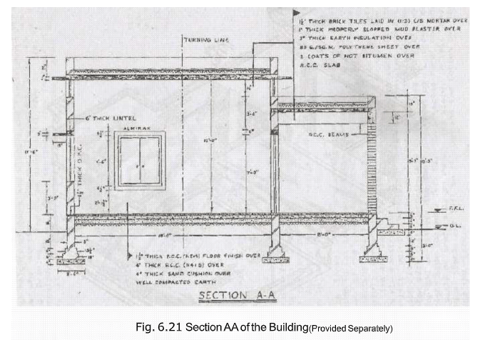
in section and in elevation may also be established from the same figure. The orthographic view of the same part of the building is shown in Fig. 6.21, cal.ted Section. Maximum details and all the dimensions are written in this view.
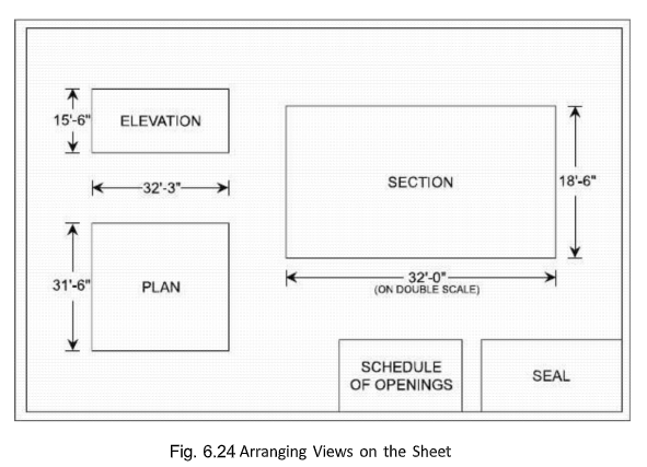
The three views are arranged on the drawing sheet according to 1st angle projection as
shown in Fig. 6.24. The division of the space for these views will be approximate. The
starting point for the plan may be considered at the bottom-left corner of the sheet about I. 1/2′ from the left border line and about the same from the bottom border line. Plan is now constructed according to its dimensions with its bottom-left point coinciding with the selected point. Elevation is drawn after completing the section just above the plan such that approximately equal spaces are left on the top and in-between the two views.
Section is drawn on the right side (because left E.V. is selected here) on the same scale or preferably on double the scale. In this case also equal spaces are left on the top and the bottom and the left and the right.

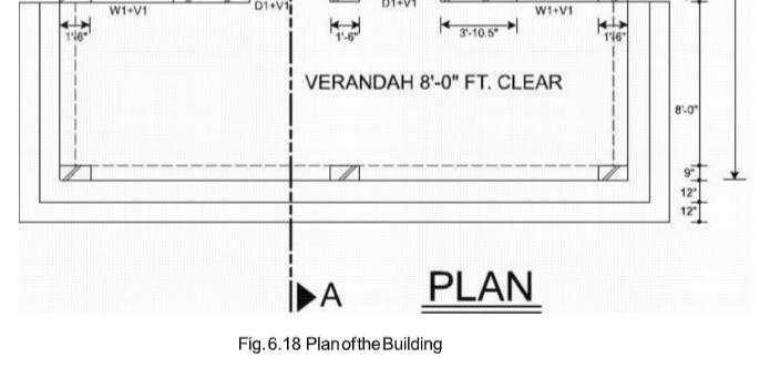

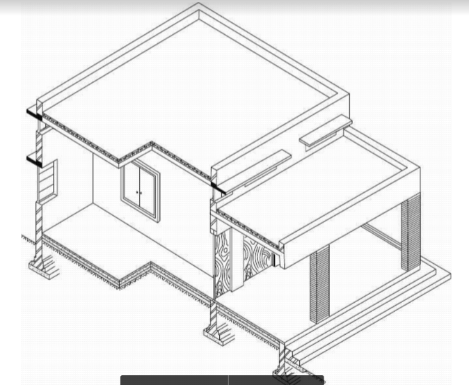
Fig. 6.20 Isometric View of the Building After Cutting for Section AA

Scale for the views must be as bigger as possible accommodating all’ the figures with
sufficient spaces in- between. First larger scale is tried and according to the dimensions of the views, it is checked whether the views will be drawn properly or not. If space is lesser for this scale, reduce the scale. Repeat the procedure until a suitable scale is selected. Schedule of doors and windows may be drawn anywhere on the sheet where space is available. This table contains information about doors, windows, ventilators and almirahs including their designation, size, quantity or number, sill level and the description in a sentence. The description includes the type of that opening and material of construction, etc.,
such as:
– Single leaf flush doors with wooden frame
– Wooden paneled double leaf doors
– Steel glazed windows with wire-gauze
– Wooden glazed ventilators.
Each view is labeled and scale is written for it. It is important to recall that plan is always drawn first showing the path of cutting to obtain the section. A Civil Engineer will then complete section while elevation is drawn at the end.


