
TO DRAW A TWO-POINT PERSPECTIVE
1. In the upper portion of the drawing sheet, top view of the station point (SP), the picture
plane (PP), and the object are drawn as shown in Fig. 5.9. The station point should be
located at a point from which the object can be best described. In two- point perspective,
the location of the station point (SP) in the top view should be slightly to the left of the
center of the object and at such a distance that the object can be viewed at a glance
without turning the head. Far that, a cone of rays with its
vertex at SP and having a total included angle of 30 ° should entirely enclose the
object. Alternatively, the distance of the station point from the picture plane may be taken equal to about twice the greatest dimension of the object for obtaining good view of the perspective. Picture plane is commonly placed in-between the object and the station point and its distance from the object controls the scale of the perspective. In practice, however, the object is usually assumed with its front corner lying in the picture plane. Top view of the object is drawn oriented at any angle to the picture plane in order to emphasize the desired shape, mostly one side is considered to be at an angle of 30° with the picture plane, see the figure.
2. Just below the top view, front view is drawn showing picture plane, horizon plane and ; round plane, the later two being represented by the horizon and the ground line
respectively, whereas, the picture plane coincides with the plane of the paper and the
perspective is drawn on it. The horizon is drawn at a distance above the ground line
representing the altitude of the station point above the ground. For small objects such
as machine parts, the station point is assumed slightly above the top of the object. For
buildings, the station point is usually taken at a normal standing height of about 5 ft. above the ground plane. The axis of vision is represented by a point on the horizon containing the station point and the center of vision.
3. To measure the height dimensions, front view or end view of the object may also be
drawn on any side of the front view for the planes assuming the object to be placed on
the ground.
4. The vanishing point for any horizontal surface can be found by looking at an infinitely
distant point on the same surface extended while standing at the station point. The visual
ray will nearly be parallel to the surface and, in top view, its piercing point with the picture
plane will locate the vanishing point. Hence, vanishing point is
actually the perspective of the infinitely distant point on the picture plane. Thus, in Fig.
5.9, the line SP to R is parallel to the edge 1-2 of the object and R is the top view of the
piercing point with the picture plane. Point P is then projected to the horizon line
indicating front view of the vanishing point for 1-2 and all edges parallel to it and is
called right vanishing point (VR). Similarly left vanishing point (VL) can also be located in
the top view and the front view.

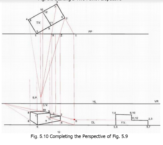
5. To locate any point on the perspective, its horizontal position and its height from the
ground should be known. point is located in the perspective horizontally by drawing
visual ray from SP to that point in the top view and projecting down the piercing
point of this ray with the picture plane to the plane of the perspective in the F.V. For
example, in Fig. 5.10, visual rays are drawn from SP to the points 3 and 2 on the object in
the top view, the piercing points on the picture plane being X and Z. These piercing
points are then projected to the frontal view locating the required points on the
perspective if their height is also known as discussed in paragraphs 6 and 7.
6. All heights behind the picture plane are foreshortened in the perspective and only
those lying in the picture plane will appear in their true length. For this reason, al’.
measurements must be made in the picture plane. The point, whose height is to be
found out, is brought forward to the picture plane along some established line in the top
view. A vertical line is then drawn upto the ground line which is called a
measuring line, the true height can be measured over it. The point obtained
according to the actual height is then joined with the vanishing point to get the
height at any distance behind the picture plane. For example, to find out heights of
points 3 and 2 in the perspective, line 3-2 is extended in the top view until it pierces PP
at the point
The point T is then projected downward, the line TS being the measuring line for all
the vertical dimensions of the face 2-3-6-7. The heights of points 3 and 2 are now
measured directly starting from the ground line or are transferred from the elevation
to obtain point ‘S . The line S-VL is the perspective of a line of infinite length
containing the perspective of the line 3-2 and it can give the height of any point on
the line 3-2 in the perspective.
7 . The intersection of the lines obtained in the paragraphs 5 and 6, showing
horizontal position and height, locates the point in the perspective. For example, in Fig.
5.10, the intersection of the line S-VL with the position lines of the points 3 and 2 will
locate the points.
8 . All the points can be located in the same way and the perspective can be
completed. The perspective may be drawn by using a single vanishing point,
however, the other vanishing point provides a check for the accuracy of the construction.


