

PICTORIAL SKETCHING
ISOMETRIC SKETCHING
An isometric sketch, although a pictorial, or three- dimensional drawing, is not drawn as
an object appears to the eye. It is made according to the actual dimensions as far as
possible. For this reason, it often looks unnatural or distorted. However, because it can
be dimensioned and it is easy to draw, an isometric sketch is preferred in
engineering works.
Along the lines called isometric lines, shown in Fig. 5.1, the dimensions vary in a fixed
proportion, the isometric lengths are 0.814 of the true lengths. If instead of shortened
isometric lengths, the true lengths are adopted, the view obtained will be exactly of the
same shape but larger in proportion. Due to the convenience in construction and
the advantage of measuring the dimensions directly from the drawing, it has
become a general practice to use the natural scale instead of the isometric scale. For
the lines which are not parallel to the isometric axes, called non- isometric lines, the
dimensions are not reduced according to any fixed ratio. Measurements should
always be made on isometric axes and the non-isometric lines are drawn by locating their ends on the isometric planes and then by joining them.
To draw isometric sketch of an object, assume it to be enclosed in an isometric box
having length, width and height equal to the overall length, width and height
dimensions of the object to be drawn. Coincide one vertical edge of this box with the
vertical isometric axis and show the horizontal edges on the 30-degree lines
according to the length and width dimensions, as shown in Fig. 5.2.
After construction of the rectangular box, the ends of the non-isometric lines are
located by measuring on the surface of the box. This method of drawing an isometric
view is termed as box method. Offset method should be used for the objects in
which ends of the non-isometric lines do not lie in isometric planes. Perpendiculars
are dropped from each end of the non-isometric lines to any of the isometric planes.
The points at which the perpendiculars meet the planes are located on the sketch
and from there the required offsets are drawn.

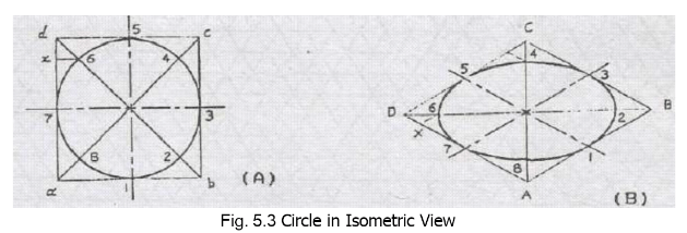
To Sketch An Ellipse Representing a Circle
A circle may be drawn in isometric projection by enclosing it in a square. An
isometric plane is drawn to represent the square, the mid-points of the sides of the
square are joined together to give the center-lines of the circle. These four points, 1, 3, 5 and 7, represent the points of the circle at 900 angle, as shown in Fig. 5.3.
Four more points showing intersection of the diagonals with the circle may be
obtained by the offset method. To plot point ‘6’ in the isometric sketch, its projection on line ‘ad’ may be drawn locating point ‘x’ in A-part of the figure. On line DA in B- part of the figure, the equivalent point ‘X’ may be located by measuring the distance equal to ‘dx’. An offset may now be drawn parallel to the line DC having a length equal to x6,
point-6 is thus located. A smooth curve drawn through all points, numbered from I
to 8, will be the isometric projection of the circle which will actually be an ellipse.
Isometric paper, as shown in Fig. 5.4, may also be used to draw isometric sketches
very quickly.
Example of Isometric Sketch From Orthographic Views
The three orthographic views are given for an object in Fig. 5.5 (A) and its isometric
sketch is to be drawn on an isometric paper. Draw rectangular box on the isometric
paper according to the total length, width and height of the object. Length dimensions
for all the parts are to be taken from the front and the top views of the object, width
dimensions from the top and the end views, and height dimensions from the front
and the end views which may be transferred to the isometric axes. Draw curve 4 using
the procedure discussed in section 5.1.1, curve 1-3-2 may now easily be drawn seeing
the shape of the inner curve. Similarly draw curve 5-7
according to the procedure and curve 6-8 by looking at the shape of the curve 5-7.
Locate all other points and properly join to get the isometric view.


