

TYPES OF SEECCTIONS
Depending upon the path of cutting an object and the use of a particular sectional view,
there are following types of sections:
Full Section
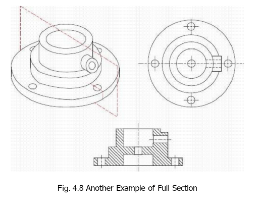
A full section entirely across the is one in which the cutting passes object so that the resulting view is completely in section. The cutting plane may be straight or it may change direction so as to include all the important inner features. Exterior shape of the object is not described in this type of section and an additional simple orthographic view may be required for that. When more than one sectional views are to be drawn from different directions, the object is considered to be complete and independent of other cuttings for a particular cutting plane, as shown in Fig. 4.B. Part-B shows the portion remaining for one sectional view and part-C for the other sectional view, whereas, part-D is the orthographic drawing of the same object with the front and the side views shown as full-sectional views. The change in plane direction for an offset cutting plane is not shown on the sectional view by full line because the cutting is purely imaginary and actually no edge is present in the object at this position.

That means, only the hidden features are made visible by sections but no extra
features are to be created. Sometimes we draw a turning line, having the same
symbol as that of a center-line, in the sectional view to describe this directional
change in the path of cutting. A full section taken along the length of the object is
called a longitudinal section and a full section taken perpendicular to the length,
along the width, is called a transverse section.
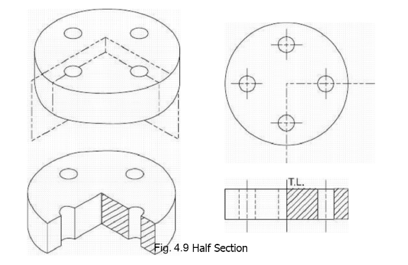
Half Section
Half section is used for symmetrical objects, the cutting is imagined to start from one end extending halfway across upto the line of symmetry of the object and then coming
forward, removing approximately quarter portion, the remaining part is then drawn by
orthographic principles. In case of half section, one half of the view is drawn in
section and the other half as a regular exterior view. A half section has the advantage of
showing both the interior and exterior of the object on a single view. Change in plane-
direction for the offset of the cutting plane is not shown because no edge exists on the
object at the center. However, axis of symmetry for the object is shown by a center line
which separates the simple orthographic and the sectional parts of the view.
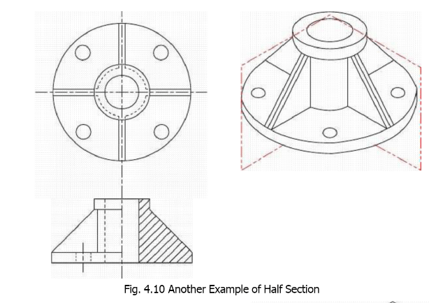
If an object is cut by a plane and the two pieces thus formed are mirror image of
each other, the object is said to be symmetrical about that plane. In other words, for
symmetrical objects, the left and the right parts of the object around the plane of
symmetry should be exactly alike. If there exists only a single plane about which an
object is symmetrical, the object is called bilaterally symmetrical. Radial symmetry
means that the object is symmetrical about all vertical planes passing through its
center. In half section, say inner details are shown in the left sectional part of the
view, then, we know, by the definition of the symmetry, that the same inner details
are present on the right side of the object. Similarly, the exterior of the object shown
in the right side of the view will be the same as that for the left side. Hence only one
view will describe the outer as well as the inner details of the object.
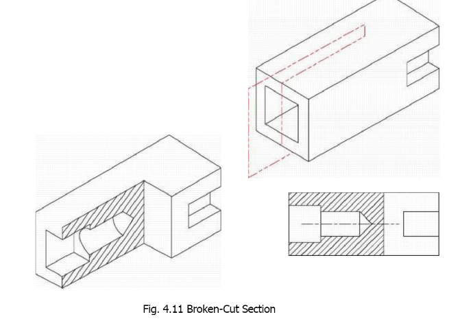
Broken-Out Section
In case of a broken-out section, the cutting starts from one end, the cutting plane is
extended inside the object only so far. as needed, and the outer part of the object is
then thought of as broken-off. The resulting orthographic view will partially be in
section separated from the exterior view by a wavy line representing the break. This
section is generally used when one part of the object has more important inner
details with no or less important exterior features while the other part has no inner
construction but possesses important features on the outer surface. The advantage ol a
broken-out section is the saving in space on the sheet and in time to draw extra views,
one view may describe the outer as well as inner details even for non-
symmetrical objects. Broken-out section is similar to a half section with the difference that
position of the cutting plane is fixed in case of half section.
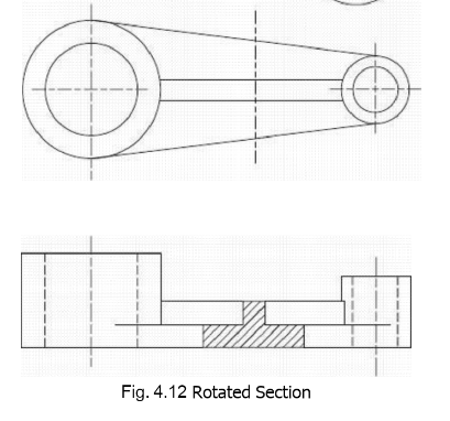
Rotated or Revolved Section
A slice of negligible thickness is obtained by assuming two vertical cuttings very
close to each other through the part to be described, view of this slice is obtained as a
section which is then rotated through 900 and is drawn onto the other simple
orthographic view, as shown in Fig. 4.12. The center-line of the slice, in its final
position, should be in line with the cutting plane. Whenever the regular view outline
interferes with the section, the view is broken. This type of section is used to describe the
shape of small parts that would otherwise be difficult to show and the main
advantage is that extra complicated views may be avoided. When this type of section
makes the simple orthographic view unreadable, it should not be used, removed
section is preferable in such cases.

Removed Section
In case of a removed section, a slice of negligible thickness is considered from inside the
object and instead of drawing its shape on any regular orthographic view, it is
removed to some adjacent place and is separately drawn there.
The cutting plane should always be indicated with reference letters in case of a
removed section to identify the section whenever needed. The main advantage as
compared with a rotated section is that the regular views are not disturbed and a
number of different sections may be drawn for an object. Further, details behind the
cutting plane are eliminated in both rotated and removed sections, making these
views much simpler.
Assembly Section
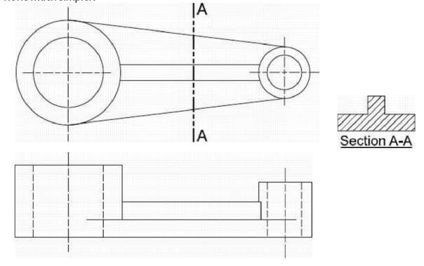
Fig. 4.13 Removed Section
Assembly drawings are used to assemble various parts to make a machine and the
purpose of an assembly section is to reveal the interior of a machine or structure so that the relative position of the separate parts can be clearly shown.
In case of assembly sections, separate parts are not described completely because
their detailed drawings are separately prepared.
Auxiliary Section
For an important part of tr. object inclined to the principal planes of projection,
inclined cutting plane may be considered to pass through it, and then normal view of that part may be drawn on a picture plane parallel to the cutting known as auxiliary section.
This type of section is needed to indicate the actual dimensions of the inclined
part.
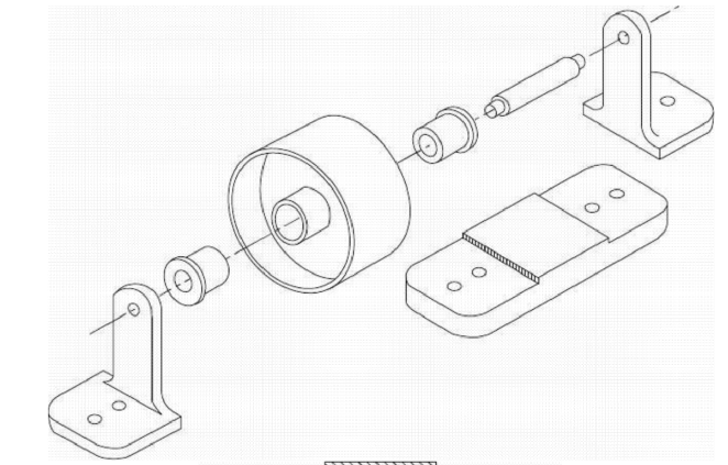

Fig. 4.14 Assembly Section
Fig. 4.15 Auxiliary Section


