
Design Loads & Load Combinations
Lecture 2
Concrete Technology
Specification & Codes
These are rules given by various organizations in order to guide the designers for safe and economical design of structures
Various Codes of Practices are
-
ACI 318 By American Concrete Institute. For general
concrete constructions (buildings)
- AASHTO Specifications for Concrete Bridges. By American Association of State Highway and Transportation Officials.
- ASTM (American Standards for Testing and Materials) for testing of materials.
-
ASCE 7 (American Society of Civil Engineers) for loads and design criteria for buildings
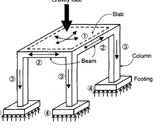
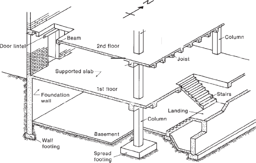
Design Loads/ Load Patterns
Dead Load
“The loads which do not change their magnitude and position w.r.t. time within the life of structure”
Dead load mainly consist of superimposed loads and self load of structure.
-
Self Load
It is the load of structural member due to its own weight.
- Superimposed Load
It is the load supported by a structural member. For instance self weight of column is self load and load of beam and slab over it is superimposed load.
• • • •
•••
••• •
•• •• •
•••• •••• •
Spandirel .· —
beam
Column
0· 1s t slab
• •• • ••
.L…-….-
B -am ·
Slab on grade7
Live Load
Design Loads
“Live loads consist chiefly of occupancy loads in buildings
and traffic loads on bridges”
Their magnitude and distribution at any given time are uncertain, and even their maximum intensities throughout the life time of the structure are not known with precision.
Values of live loads are specified in the codes
-
| Densities of Important Materials | |
|
Material |
Density (Kg/m3) |
| PCC |
2300 |
| RCC |
2400 |
| Brick masonry |
1900-1930 |
| Earth/Sand/Brick ballast |
1600-1800 |
Intensities of Live Loads
| Occupancy / Use |
Live Load(Kg/m2) |
| Residential/House/Class Room |
200 |
| Offices |
250-425 |
| Library Reading Room |
300 |
| Library Stack Room |
730 |
| Warehouse/Heavy storage |
1200 |
Basic Design Equation
Max. Service Load = Max. Internal Resistance x F.O.S
Factor of Safety
F.O.S. = Max. Service Load / Max. Failure load
Following points are relevant to F.O.S
1 It is used to cover uncertainties due to
. 1. Applied loads
- Material strength
- Poor workmanship
- Unexpected behavior of structure
- Fabrication
- If F.O.S is provided then at service loads deflection and cracks are within limits.
- It covers the natural disasters.
Ultimate Strength Design (USD)/LRFD Method
Strength design method is based on the philosophy of dividing F.O.S. in such a way that Bigger part is applied on loads and smaller part is applied on material strength.
(Applied Load x F.O.S.1) < (Material Strength x F.O.S.2)
Ultimate Strength Design (USD)/LRFD Method
(contd…)
Where
U < ΦSn
Sn = Nominal Strength
ΦSn = Design Strength
Φ = Strength Reduction Factor
U = Required Strength, calculated by applying load factors
For a member subjected to moment, shear and axial load:
ΦMn ≥ Mu ΦVn ≥ Vu ΦPn ≥ Pu
Allowable Strength Design (ASD)
In allowable strength design the whole F.O.S. is applied on material strength and service loads (un-factored) are taken as it is.
Service Loads < Material Strength / F.O.S
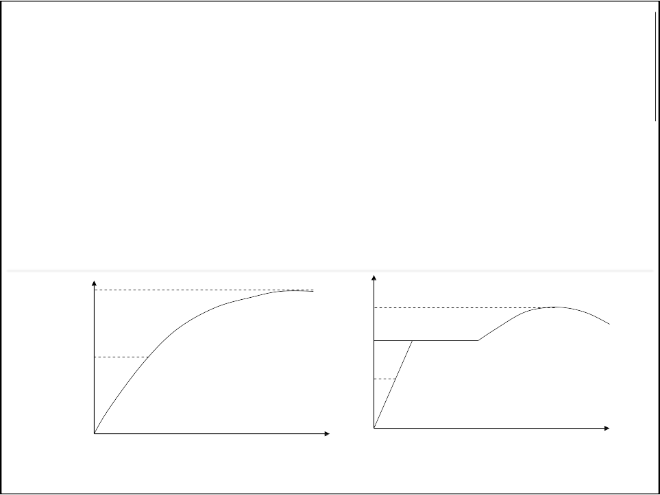
In both Allowable strength design and Ultimate strength
design analysis carried out in elastic range.
fc‘
Stress
fc‘/2
Concrete
fu
Stress
fy
fy/2
Steel
Strain
Plastic Design
In plastic design, plastic analysis is carried out in order to find the behavior of structure near collapse state. In this type of design material strength is taken from inelastic range. It is observed that whether the failure is sudden or ductile.
Ductile failure is most favorable because it
gives warning before the failure of structures
Objectives of Designer
There are two main objectives
- Safety
- Economy
Load Combinations (F.O.S1)
To combine various loads in such a way to get a critical situation.
Load Factor = Factor by which a load is to be increased x probability of occurrence
1. 1.4D
2. 1.2D + 1.6L
3. 1.2D + 1.6L + 0.5Lr
4. 1.2D + 1.6Lr + (1.0L or 0.8W)
Where
D = Dead load
L = Live load on intermediate floors Lr = Live load on roof
W = Wind Load

(F.O.S2)
Strength Reduction Factor / Resistance Factor, Φ
| Strength Condition | Strength Reduction Factor |
| Tension controlled section (bending or flexure) |
0.9 |
| Compression controlled section | |
| Columns with ties |
0.65 |
| Column with spirals |
0.75 |
| Shear and Torsion |
0.75 |
THANK YOU


