
Adding the Kitchen Pass-Through and Custom Countertop
- Open the RL2-5 file. Save the file as RL2-6.
- Open the south kitchen elevation view by double-clicking on the bottom arrow of the interior elevation symbol.
- Click on the edge of the south kitchen wall.
- Click on the Edit Profile tool in the Mode panel.
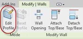
Edit Profile Tool
- Click Close if the Alert Box Appears.
-
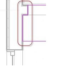
Using the Draw panel tools, create a rectangular opening as shown. Locate the
 right side of the opening approximately 6″ from the right magenta line. You may use a reference line for the 6″ distance.
Kitchen Wall Opening Dimensions
- Click the Green Check. Now there is a location for the eating bar that you will add in the next set of steps.
Adding the Custom Counter Top
- Switch to First Floor view.
- Zoom in on the south side of the kitchen.
- You will now see the opening for the pass-through in the south kitchen wall.
Opening in South Kitchen Wall
- Go to the Component Tool and select Model In-Place.
- Choose Casework for the Family Category and Parameters.
- Name the Family, Eating Bar Counter Top.
- Click on the Extrusion tool in the Forms panel.
-
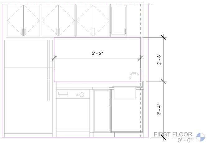
Set the Extrusion End to 3′-5 1/2″, Extrusion Start to 3′-3 1/2″, and the
Material to Counter Top.
- Draw the shape as shown.
You do not need to include the dimensions.
If the dimensions appear too large, you may wish to change the scale of the view.
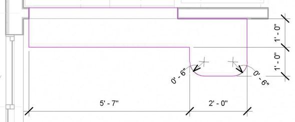
Eating Bar Dimensions
- Click the Green Check.
Click the second Green Check to finish the Model.
Completed Eating Bar
- After the completing the Eating Bar, you may notice that the left side of the bar should be flush with the wall. This will involve moving the window down to allow for the depth of the counter top.
Move the window down so that the top edge is 4″ below the bottom edge of the counter.
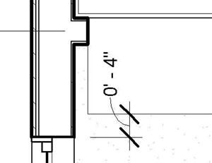
This will be far enough so the window trim will clear the edge of the counter top.
Window Aligned with the Counter Top
The dimension is for reference only.
- Click once on the countertop and click on the Edit In-Place tool.
- Click on the countertop again and then the Edit Extrusion tool.
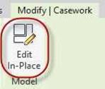
Edit In-Place Tool
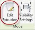
Edit Extrusion Tool
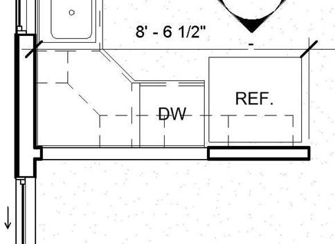
- The countertop edge will turn magenta. Modify the shape in the area shown.
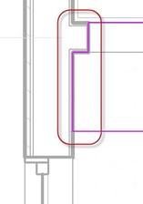
Modified Counter Top Shape
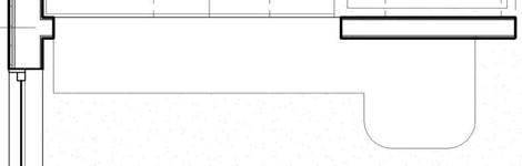
- Click the Green Check twice to complete the modification. Refer to the example below for the completed version of the kitchen area and garage appliances.
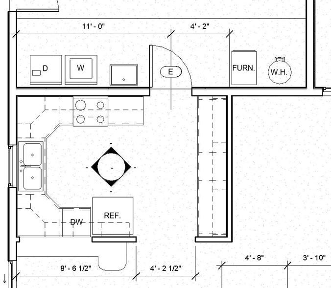
Completed Kitchen and Garage Cabinetry, Appliances, and Fixtures
- This is the end of Part 6. Save your file as RL2-6.
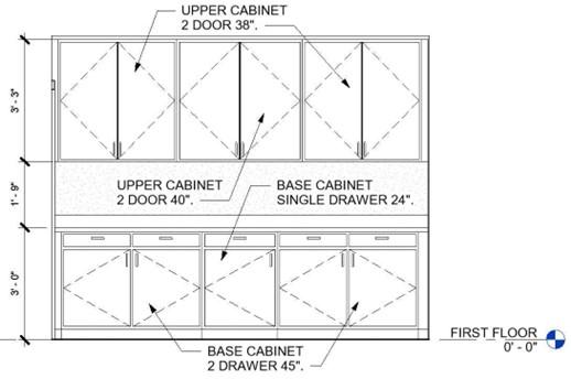
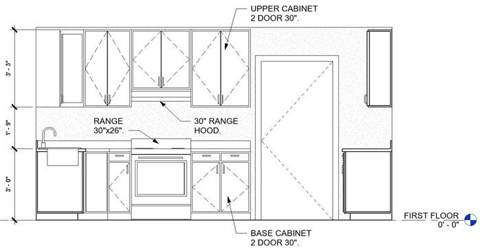
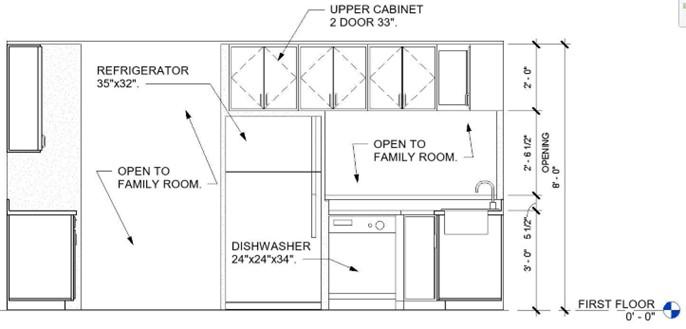
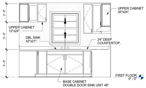
Completed Versions of the Kitchen Interior Elevations
These are the completed views of the kitchen elevations. Notes have been added. You may add the notes at the end of this tutorial or when you complete the portfolio at the end of the book. In the next tutorial part, you will cover the methods for adding the text notes and modifying the dimension style. Later in the book you will add tile and baseboards in the kitchen.
Interior Elevation View (Kitchen – East)
Interior Elevation View (Kitchen – North)
Interior Elevation View (Kitchen – South)
Interior Elevation View (Kitchen – West)


