Adding the Reference Planes and Aligning the Lights,
Constraining the Location
In this part you will add reference planes for each row and column of light fixtures. You will then align and lock the fixtures to the planes. Lastly, you will control the location of the lights by dimensioning the reference planes.
- Open the WU2-2 file. Save the file as WU2-3.
- Click on the Reference Plane tool in the Architecture tab, Work Plane panel.
- Draw a reference plane to the right of each column of lights.
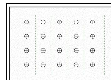
Reference Planes Added
- Click on the Align tool in the Modify tab, Modify panel.
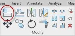
Align Tool
- Align the fixtures to the Reference Planes.
Check the Multiple Alignment checkbox to keep from having to click the reference plane each time.

Multiple Alignment Checkbox
- Click the Reference Plane then the Vertical Line.
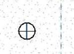
Reference Line and Vertical Line
- Once the light fixture moves onto the line, click the padlock.
- Repeat the process for the rest of the column. Be sure to click the padlock for each light.
- Repeat the process for the other four columns.
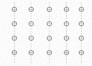
Column Locked
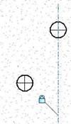
Alignment Locked

Column Locked
- To test the locked alignment, move the reference plane. The fixtures will move with the line.
-
Draw four additional reference planes horizontally below each row.
Lock the fixtures in each row to the reference plane.
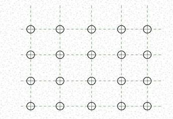
Rows Locked
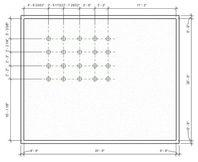 Add a row of dimensions as shown. For the columns and the rows. Your dimensions may be different.
Dimensions Added
- Add a second row of dimensions above the first.

Second Row of Dimensions Added
- Click on the second row.
Click on the EQ toggle above the row.
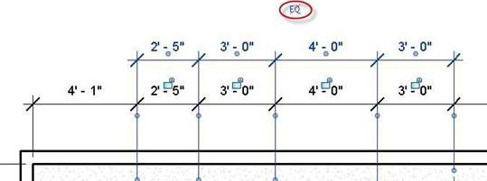
EQ Toggle
- The columns will be equally spaced from each other.
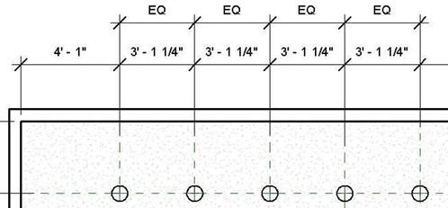
Columns Equally Spaced
- Click on the first vertical reference plane.
Set the first dimension to 3′-6″. Repeat for the last vertical plane.
The lights will remain equally spaced.
Select and stretch the reference plane by dragging the endpoint through the fixtures.
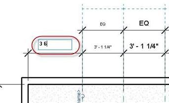
Change the First Dimension to 3′-6″
- Change the second dimension to 3′-6″.

Second Dimension Changed to 3′-6″
- Repeat the process for the four rows.
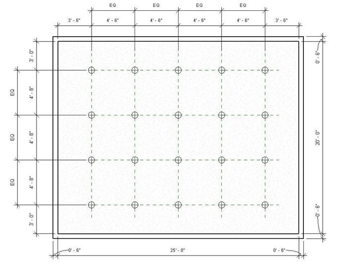
Rows Aligned and Located
- Try changing the end dimensions to see how the fixtures change location.
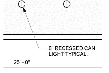
- To add the note for the light, click on the Text tool in the Annotate tab, Text panel.

Text Tool
- Then click on the Two Segments tool in the contextual tab.
- Click first at the edge of the light and then where the text will be located.
Add a short horizontal line before the text location.
Type in the note as shown.
- Next you will change the arrowhead to a filled in type.
After placing the note, select it and click the Edit Type button in the Properties dialog box.

Two Segments Tool
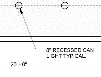
Text Note Added
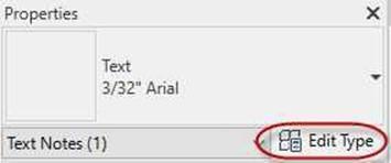
Edit Type Button
- The Type Properties dialog box opens.
Next to the Leader Arrowhead parameter, change the value to Arrow Filled 30 Degree.
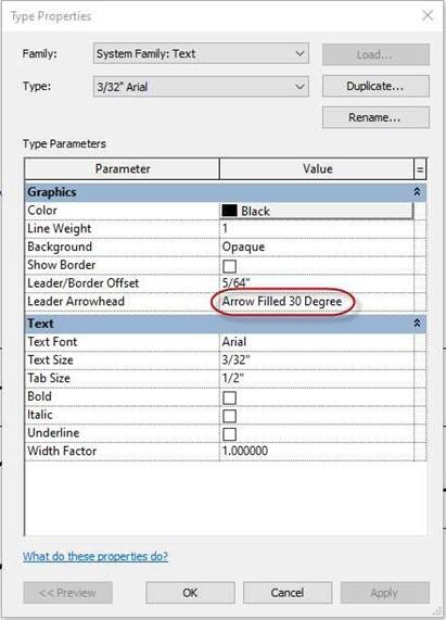
Type Properties for the Text Style
This is the end of Part 3. Save your file


