The functions of various dimensioning tools are discussed below, one-by-one:
Dimension [ DIM
This tool is used to create the dimensions according to the entity selected.
Click Annotate > Dimensions > Dimension on the ribbon.
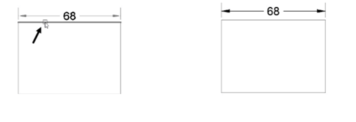
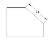
Select a line entity, move the cursor and click to place the linear dimension, as shown.
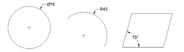
Select a circle, move the cursor and click to place the diameter dimension, as shown.
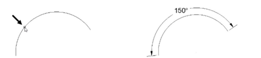
Select an arc, move the cursor and click to place the radial dimension, as shown.
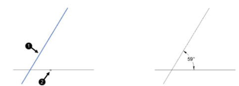
Similarly, select two lines and place the angular dimension, as shown.
Linear
This tool is used to create horizontal and vertical dimensions.
Click Annotate > Dimensions > Dimension > Linear on the ribbon.
Select the first and second points of the dimension.
Move the cursor in horizontal direction to create a vertical dimension (or) move in the vertical
direction to create a horizontal dimension.
Click to place the dimension.
Aligned
This tool is used to create a linear dimension parallel to the object.
Click Annotate > Dimensions > Dimension > Aligned on the ribbon.
Select the first and second points of the dimension line.
Move the cursor and click to place the dimension.
Angular [ DAN
This tool is used to create an angular dimension.
Click Annotate > Dimensions > Dimension > Angular on the ribbon.
Select the first line and second line, as shown.
Move the cursor and place angle dimension, as shown.
 To create an angle dimension on an arc, select the arc and place the dimension.
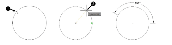
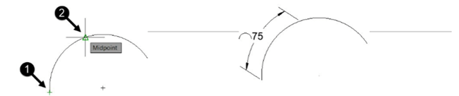
To create an angle dimension on a circle, select two points on the circle and place the angle
dimension, as shown.
Arc Length
This tool is used to dimension the total or partial length of an arc.
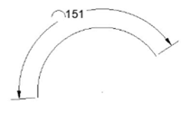
Click Annotate > Dimensions > Dimension > Arc Length on the ribbon.
Select an arc from the drawing.
If you want to dimension only a partial length of an arc,
select Partial option from the command line.
Next, select the two points on the arc, as shown.
Move cursor and click to place the dimension.
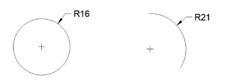
Radius [ DRA
This tool is used to create a radial dimension of a circle or an
arc.
Click Annotate > Dimensions > Dimension > Radius on the ribbon.
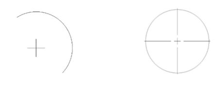
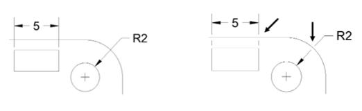
Select a circle or an arc and place the dimension, as shown.
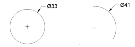
Diameter
This tool is used to dimension a circle or an arc, as shown.
Click Annotate > Dimensions > Dimension > Diameter on the ribbon.
Select a circle or an arc and place the dimension.
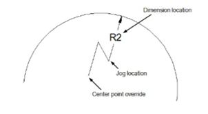
Jogged
It is used to create jogged dimensions. A jogged dimension is created when it is not possible to show the center of an arc or circle.

Click Annotate > Dimensions > Dimension > Jogged on the ribbon.
Select an arc or circle.
Select a new center point of the circle or arc.
Locate the dimension and the jog location.
Ordinate
It is used to create ordinate dimensions based on the
current position of the User Coordinate System (UCS).
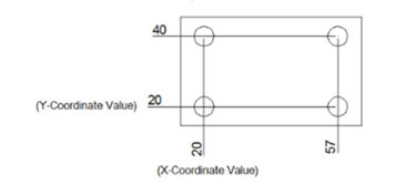
Click Annotate > Dimensions > Dimension > Ordinate on the ribbon.
Select the point of the object.
Move the cursor in the vertical direction and click to place the X-Coordinate value.
Move the cursor in the horizontal direction and click to place the Y-Coordinate value.
Continue
It is used to create a linear dimension from the second extension line of the previous dimension.
Create a linear dimension by selecting the first and second points.
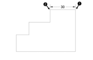
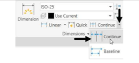
Click Annotate > Dimensions > Continue on the ribbon; a chain dimension is attached to the cursor.
Select the third and fourth point of the chain dimension.
Place the chain dimension. Next, right-click and select Enter.
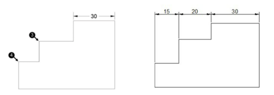
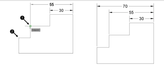
Baseline
It is used to create dimensions by using the previously
created dimension.
Create a linear dimension, as shown.
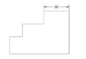
Click Annotate > Dimensions > Continue > Baseline on the ribbon.
Select the base dimension, if it is not already selected.
Select the other two points for the baseline dimension.
Next, right-click and select Enter.
Dimension, Dimjogline [ DJL
It is used to create a jogged linear dimension.
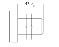
Click Annotate > Dimensions > Dimension, Dimjogline on the ribbon.
Select the linear dimension to add jog.
Specify the location of the jog on the dimension.
Center mark
It is used to place a center mark inside a circle or an arc.
The type of center mark will depend on the value of the
DIMCEN variable. For a positive value, center marks are created and for a negative value,
centrelines are created.
Click Annotate > Centerlines > Center Mark on the ribbon.
Select an arc or a circle; the center mark will be placed at its center, as shown.
Quick Dimension [ QDIM
It is used to dimension one or more objects at the same time.
Click Annotate > Dimensions > Quick Dimension on the ribbon.
Select one or more objects from a drawing.
Right-click and place the dimensions.
Adjust space
It is used to adjust the space between linear and
angular dimensions.
Click Annotate > Dimensions > Adjust Space on the ribbon.
Select the base dimension from which the other dimensions are to be adjusted.
Select the dimensions to be adjusted.
Right-click to accept.
Enter the space value or select the Auto option; the dimensions will be adjusted with respect to
the base dimension.
Break
It is used to create breaks in dimension, extension, and leader lines.
Click Annotate > Dimensions > Break on the ribbon.
Select the dimension to add a break.
Select the cutting object; the dimension will be broken by the cutting object.
Right-click to exit the tool.
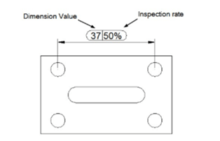
Inspect
It is used to create an inspection dimension. The inspection dimension describes how frequently the dimension should be checked to ensure the quality of the product.
Click Annotate > Dimensions > Inspect on the ribbon; the Inspection Dimension dialog box
appears.
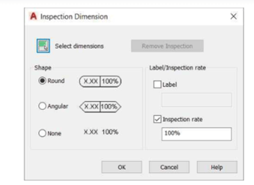
Click the Select dimensions button on the dialog box and select the dimension to apply the
inspection rate.
Right-click to accept.
Select the shape of the inspection from the Shape section.
Enter the Inspection rate. 100% means that the value will be checked every time during the
inspection process. 50% means half the times.
If required, select the Label check box and enter the inspection label.
Click OK.
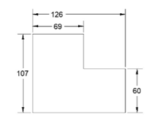
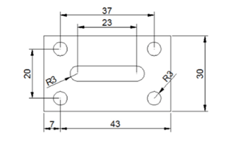
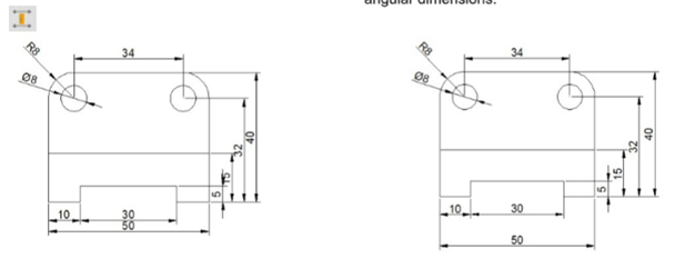
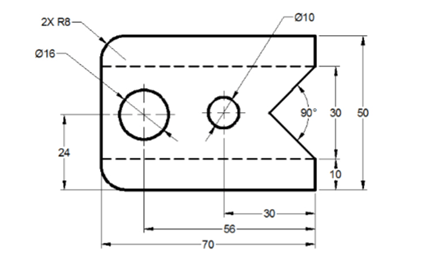
Example:
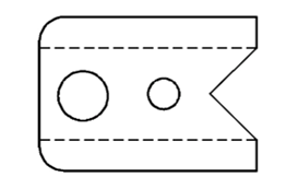
In this example, you will create the drawing as shown below and add dimensions to it.
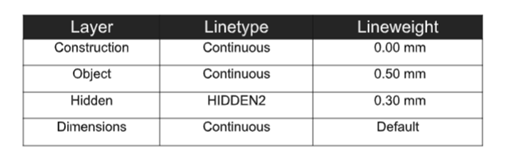
Create four new layers with the following settings.
Set the maximum limit of the drawing to 100,100.
Click Zoom All on the Navigation Bar.
Create the drawing on the Object and Hidden layers.
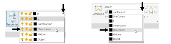
 Select the Dimensions layer from the Layer drop-down in the Layer panel of the Home tab, as shown.
Alternatively, you can select it from the Layer drop down available in the Dimensions panel of the
Annotate tab, as shown.