
Shear walls
General
Shear walls are vertically oriented elements that apart from their ability to bear vertical loads, they also limit the horizontal deformations of the structural frame. Since as a rule, they carry gravity loads, their large size is not entirely required. On the other hand, that large size is abso- lutely necessary in order for them to resist the horizontal seismic forces. Ground earthquake motions cause severe flexural and shear stresses to the shear walls. These stresses can only be carried by a strong and properly placed, inside their entire mass, reinforcement.
Shear wall refers to any vertical element with a length to thickness ratio of 4 or more. The clas- sification of an element as shear wall determines the way that the reinforcement will be placed inside its concrete mass. In order for a shear wall to behave in the required way, it must have two columns embedded inside its ends or otherwise called two boundary elements.
In case the shear wall does not have clearly defined boundary elements, two hidden columns are formed at the edges of the wall’s mass. Their width is equal to the shear wall’s thickness and their length must be at least equal to one and a half times the wall’s thickness (≥ 1.5b).
The boundary columns apart from assisting in the assembling of the shear wall also ensure a minimum strength capacity. During a severe seismic event, it is possible for wall consistency degradation to happen. In such a case, at the lower critical level of the building, the two embed- ded columns, with the high ductility that they have, will continue to bear the largest amount of the applied vertical gravity loads and seismic forces.
Notes:
-
Forming a 45cm column (regular or hidden), has the advantage that it is the maximum length to place a three-legged stirrup and the distance between the stirrup legs to be around 20cm as required by the regulation.
-
Forming a 40 cm column usually does not provide adequate anchorage length. On the other hand, the use of a 50cm column requires a four-legged stirrup.
Shear wall’s behavior
In the duration of a seismic event, flexural and mainly shear loads are applied to the wall. As a result, in the entire element’s surface, stresses appear along the diagonal axis. The diagonal shear stresses shift direction with the change in the earthquake shaking. These stresses are efficiently carried by the well-confined boundary columns, while in the main body of the shear wall they are carried by the double reinforcement mesh (horizontal and vertical rebars).
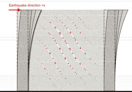
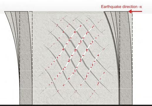
The cracks that open due to the applied seismic forces in one direction, will close when the direction changes. This will continue to happen in the entire duration of the earthquake.
Shear wall’s reinforcement
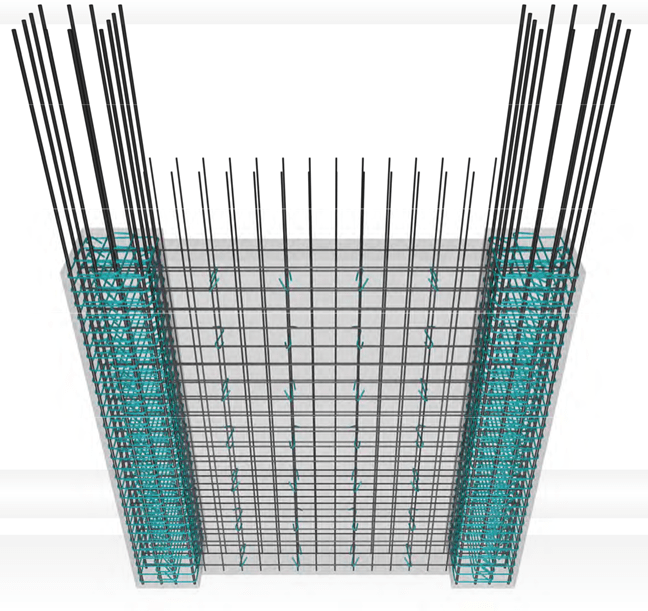
The boundary elements, either regular or hidden, are reinforced according to the rules that ap- ply to columns.
The wall body is reinforced by two parallel grates one at each face. These are called curtains and they are held together with the use of an ‘S’-shaped vertical bar. The vertical grate rebars must have a diameter at least equal to Φ10, while the horizontal rebars may even be Φ8 how- ever, as a rule, both horizontal and vertical rebars are calculated and implemented with the same diameter. The ‘S’ shaped reinforcement must be greater or equal to 4Φ8/m2 and it might even be made out of soft steel (old class S220).
When we do not want cracked surfaces e.g. in pool sides, we use narrow spaced grates with the lower possible rebar diameter.
The ‘S’- shaped reinforcement
The ‘S’-shaped bar provides antibuckling restraint to the longitudinal reinforcement. Moreover, it ensures the vertical and the horizontal rebars will continue to work together even after possible concrete spalling in case of an intense earthquake event.
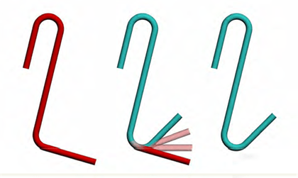
The ‘S’-shaped link is formed with one closed corner at an angle equal to 180°, or 135° and the other corner bent at an angle equal to 90°. This is necessary for its trouble-free placement. However, after its implementation the second corner must be also bent at an angle at least equal to 135°.
It is allowed to use soft steel in order to be able to bent the ‘S’-shaped reinforcement by hand.
When the vertical rebars are placed in an interior layer, then the ‘S’-shaped link must restrain the horizontal rebars to the area that they intersect with the vertical ones or even better to go around both horizontal and vertical rebars at the same time.
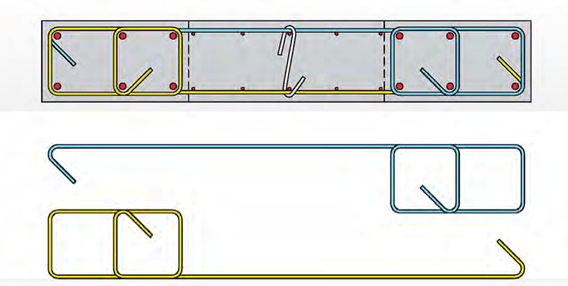
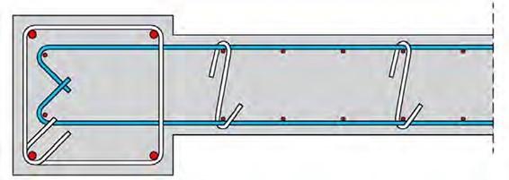
Alternatively, in an orthogonal shear wall, the reinforcement of the boundary column and the distribution rebars of the wall’s body can be implemented as two ‘Γ’ shaped parts, as shown at the following figure. The ‘Γ’ shaped parts may be formed with the use of folded mesh.
Anchoring the horizontal rebars of the shear wall’s body
-
Anchorage inside a strong boundary column
When the boundary column is strong enough and the horizontal rebars (distribution bars) get anchored inside the column’s core, a straight anchorage length can be used.
- Anchorage inside a weak boundary column
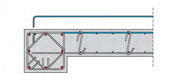
When the boundary column is weak and its width is not long enough to allow for a straight an- chorage, it is mandatory to anchor the horizontal rebars by forming a hook at their ends.
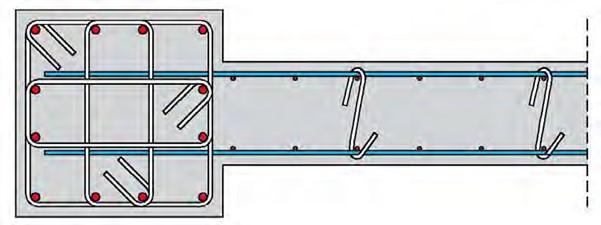
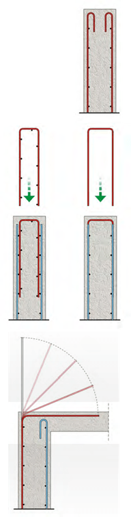
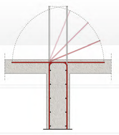
- Straight anchorage inside the core, when the boundary column is strong enough and its one face colinear with one side of the shear wall:
- case:
In this case, the disadvantage lays in the need for bending up the horizontal rebars in certain areas. For Φ8 and Φ10 bars, this can be easily done during the implementation, with the use of a bending tool; however, for larger diameters it has to be done with a bending machine.
In this case, the S’-shaped reinforcement must restraint the horizontal rebars to the point where they intersect with the vertical ones.
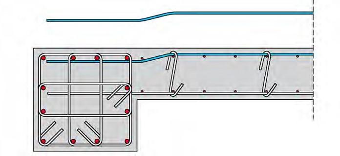
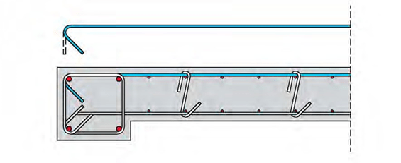
-
case:
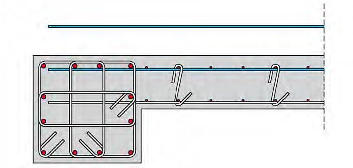
In this case, a straight anchorage is used and the horizontal rebars do not have to be bent. This increases their cover depth but since they mainly carry shear forces no serious problem arises. Moreover, the internal lever arm of the vertical rebars is diminished but only around 1cm so practically again, no problem appears.
As a conclusion, it is recommended to use a straight bar anchored inside the boundary column because apart from the other advantages, it provides the required cover depth for the ‘S’ shaped bars when they go around both the horizontal and the vertical distribu- tion rebars at the same time.
- Anchorage by encircling the boundary column and ending in a hook.
No matter if the column is strong or weak, the horizontal rebars must end in a hook which will be placed in the inside of the confined column.
 1st case: adequate straight anchorage length:
The anchorage might be achieved with a 90° hook placed inside the body of the boundary col- umn
 2nd case: inadequate straight anchorage length:
When the column’s width is not large enough to provide an adequate straight length of anchor- age, hooks bend at 45° (135°) are being used. These are either completely prefabricated so as to have 45° bend in both edges, or they are assembled on the site with horizontal rebars with ends bend in 45° and 90°. These will be alternately placed along the height.
-
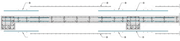
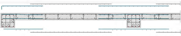
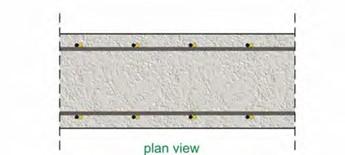
Anchorage of continuous peripheral basement shear walls
In continuous basement shear walls the difficulty in the reinforcement implementation lays in the column area. In order to overcome this difficulty straight distribution rebars may be placed there. These bars have a relatively small length. They will be lapped with the larger intermediate dis- tribution rebars and they will be wired together with the vertical ones.
It is very practical to use horizontal and vertical distribution bars in the form of a ready-to-use wire mesh. In such a case, the practices described below are being followed:
Firstly, the ‘short’ horizontal rebars (starter bars) are placed on either side of the column, fol- lowed by the implementation of the wire meshes as shown at the next page.
Notes:
If the industrial wire mesh does not fit to the shear wall’s span length then the short starter bars placed in the columns’ area might have a larger length. In such a case, the vertical distribution rebars between the end of the wire mesh and the column, are placed by hand after the imple- mentation of the mesh.
In case the column longitudinal rebar layout creates a difficulty in the implementation of the short distribution rebars, the latter can be bend at their end.
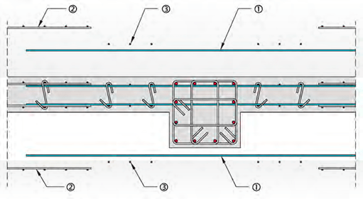
CD Short distribution column bars
a> Industrial mesh
® Additional vertical distribution bars


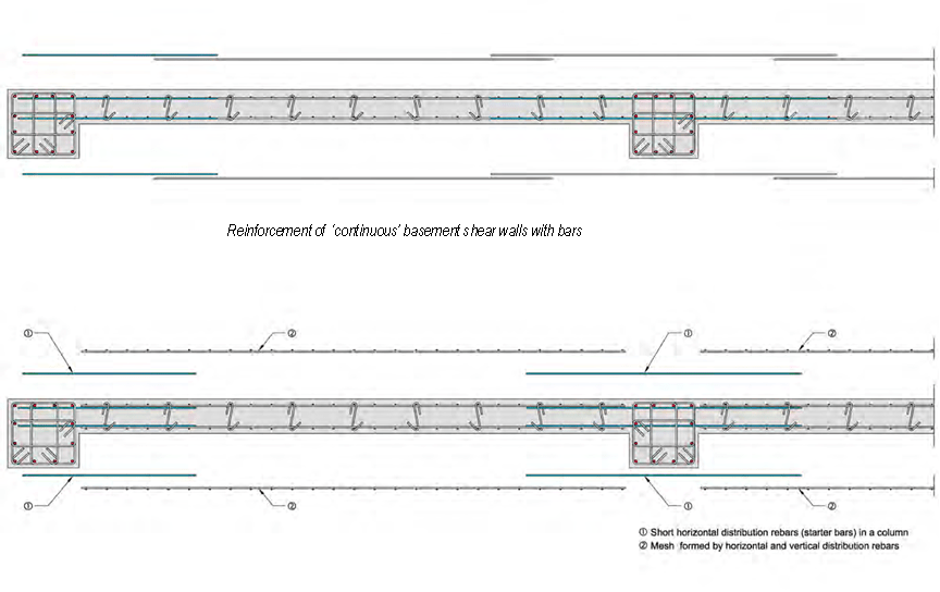
Reinforcement of ‘continuous’ basement shear walls with industrial wire meshes
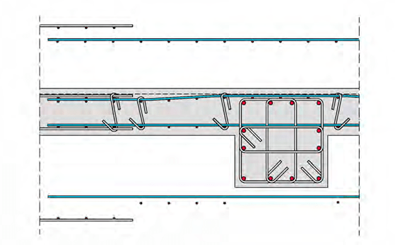
Usually, in the perimeter of the building, in the storeys above the ground, there is a seismic joint (3 to 5cm), or thermal insulation (3 to 5cm) which are not required in the basement. However, their thickness can be used in the basement shear walls to secure the cover depth and to en- able the implementation of the distribution meshes outside the column reinforcement, as shown at the following figure.
Lap-splices of vertical bars
 The rules that apply are the same with those mentioned in chapter 3.1.1 that deals with lap-splices in column rebars. However, there is one critical difference that simplifies the lapping of the vertical reinforcement placed to the shear walls’ body: there are no stir- rups thus the vertical co-linearity of the re- bars is not necessary. In walls’ bodies lap- ping is being done with the use of a simple contact lap-splice parallel to the longitudinal axis of the element.
Generally, the lap length is not extremely large because the vertical rebars’ diameter is usually small. For a typical diameter Φ10/B500c, the required lap length is equal to 67cm, 58cm and 51cm, for concrete grades C20/25, C25/30 and C30/37 respec- tively.
Note:
Theoretically, the finest solution is to lap 50% of the rebars at a time in different heights.
Anchorage of vertical rebars
 Bars must be anchored at the upper part of shear walls. This anchorage must be done accord- ing to the same rules that apply to the anchorage of column rebars. However, as a rule, it is a more simple procedure, due to the smaller diameter of the vertical reinforcement placed inside the wall’s body and also due to the possibility of rebar lapping with a contact lap-splice. Two ba- sic cases are defined, anchorage inside the shear wall’s mass and anchorage inside the adja- cent slabs’ body.
-
Anchorage of rebars in the shear wall’s mass
-
with hooks
The hooks must be formed by a bending machine with the use of the appropriate rolls (see §2.6.3). The angle of the hook might be 135 ° however, it is preferred to be 180°.
-
with an additional Π rebar
A ‘Π’ shaped bar (figure a) provides, apart from the anchoring, the proper finishing of the shear wall reinforcement. The use of a wire mesh (figure b) has a lot of advantages regarding its implementa- tion however, due to the welded distribution reinforcement, the ‘Π’ shaped bar, must be formed to fit between the two parallel vertical meshes.
This type of anchorage is preferred in most cases and especially when the accurate implementation of the wall’s body rebars along the height cannot be easily done e.g. in the case of a basement where the body rebars are implemented together with the founda- tion reinforcement.
-
Anchorage of rebars inside an adjacent slab
-
Having a slab on one side
In case the upper part of the shear wall has only one side con- nected to a slab, the outer vertical rebars, may assist in securing the fixed support of the slab.
.
An alternative solution is to place a ‘Γ’ shaped wire mesh. 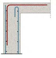
-
Having a slab on both sides
In case the shear wall has slabs on either side, its rebars can be anchored inside the slabs’ mass and at the same time they can be a part of the required slab support rein- forcement.
Finally, it is highlighted that apart from the above men- tioned solutions there is a wide range of other combina- tions.
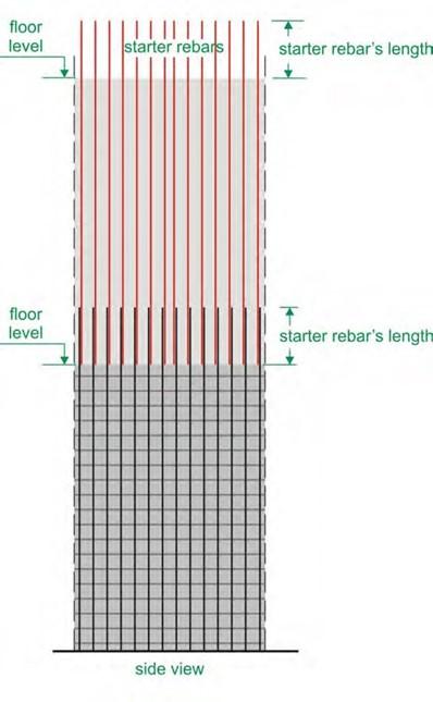
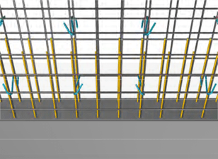
Starter bars in shear walls
The need to construct co-linear or vertical shear walls in different phases arises quite often. Most of the times the starter bars are placed in the traditional way i.e. by extending the horizon- tal rebars of the first shear wall towards the direction of the shear wall that will be constructed in a following phase.
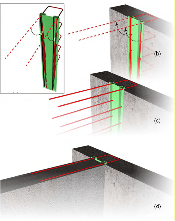
In the cases where the new shear wall will be perpendicular or co-linear with the old one and the starter bars will cause problems in further excavations or they will be damaged by handling machines, the special technique described below is being used:
- the starter bars are shaped like a hair pin, their legs are temporarily bent and they are en- cased in a standardized steel or in an impromptu (e.g. made out of polystyrene) thin box,
- the thin box is nailed upon the formwork. Then follows the implementation of the first shear wall reinforcement and finally comes the concrete casting,
- after the formworks removal, the starter bars are once again centerlined. If the encase box is an impromptu construction, it is removed.
-
the second shear wall is constructed
The four phases when adding a vertical element
This technique is used either for vertical or colinear shear walls. It is ideal when constructing a partial foundation by an excavating and concrete pouring sequence. This is used when there is danger for the adjacent building. We excavate a part of the common edge and we concrete the shear wall and its foundation. Then we excavate the next part and so on.


