
EARTHQUAKE RESISTANT BUILDINGS Reinforcement specifications of antiseismic design

Reinforcement specifications of antiseismic design
Reinforcement specifications of reinforced concrete earthquake resistant structures include the detailing specifications applied to conventional structures as well since earthquakes occur very rarely in the structures’ life span.
For a structure to be earthquake resistant it must firstly abide by the regulations regarding usual structures. However, its construction demands greater attention because the critical moment of the seismic event will test the structure’s strength capacity thus proving the need for meticulous application of all the regulations referring to reinforced concrete. Apart from the normal con- struction rules, other rules must be satisfied as well mainly regarding the vertical reinforcement like use of narrow spaced polymorphic stirrups.
The construction specifications regarding the formation and placement of reinforcement are compulsory for all structures since they are issued by the Greek Code for Reinforced Concrete (ΕKOS 2000) and the Greek Code for Seismic Resistant Structures (ΕΑΚ 2000), as well as by the equivalent Eurocodes EC2 και EC8 which constitute laws of the country. A technician most of all must comprehend their necessity and based on that must always perform his/hers prac- tices in compliance with them. The only capable force of reducing scrappiness and improvi- dence in construction is proper knowledge and not laws
In seismic resistant structures the requirement for a large amount of narrow spaced longitudinal and vertical reinforcement makes elements reinforcing a quite strenuous task. If in countries with low seismic activity the requirement for correct design implementation is taken as a fact, in earthquake prone countries, like Greece, this requirement is at least two times more important. The basic specifications of antiseismic reinforcement are four:
- the reinforcement covering,
- the minimum distance between reinforcement bars,
- the light bending of rebars
- the antiseismic stirrups.
Reinforcement covering
The reasons why rebar covering is required, are:
- Protection of reinforcement from corrosion (rusting).
- The need for adequate adhesion between the steel and concrete.
- Fire protection: the concrete that covers reinforcement protects it from deformations caused by the development of high temperatures due to fire in the building.
- The need to create cable and pipe channels without harming the reinforcement9.
Generally coverings secured by the use of plastic spacers have a considerable material pro- curement cost as opposed to their low implementation cost.
Of course it is possible to use other “common” materials as well, like pieces of marble. These although they have a low procurement cost their implementation is economically demanding. However, their largest problem is their correct application since they are placed after the posi- tioning of reinforcement and prior to the concrete casting.
In cases where visible concrete surfaces (off-form concrete or architectural concrete) is re- quired, one may use point or linear spacers made out of fiber reinforced concrete or even rebar chairs with fiber reinforced concrete tipped legs.
Covering of slabs lower reinforcement
The minimum required cover depth for slab reinforcement usually ranges between 2.0 and 3.0 cm depended on the environmental conditions present throughout the building’s service life. The 2.0 cm would apply to a dry climate and the 3.0 cm to a seaside location.
The required covering is achieved only with the use of special stands called spacers. These must not be affected by corrosion and should be placed approximately every 1.00 m.
9 Normally, an electrician or a plumber during the construction stage usually engraves channels in the elements constituting the structural frame. Inside these channels he places electric cables or pipes. However, due to design modifications, he might have to open these channels by chipping the surface of the already constructed surfaces.
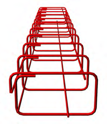
Cover depth of the slab’s lower reinforcement is secured with the use of plastic spacers.
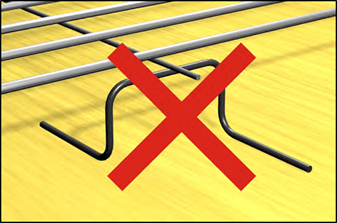
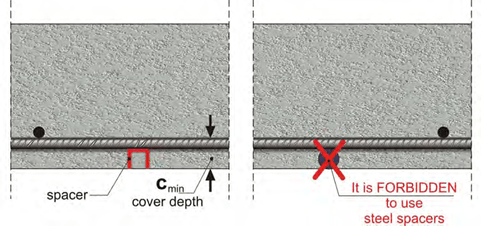 The simplest solution for providing the necessary cover depth of the reinforcement is special plastic spacers like the ones shown in the above figure. Usage of steel rebar spacers is forbid- den as they are highly susceptible to corrosion.
When rebars corrode the resulting volume expansion leads to concrete spalling and conse- quently to the cracking of the plaster. Extensive deterioration affects not only the residents’ safety but also the structure’s service life.
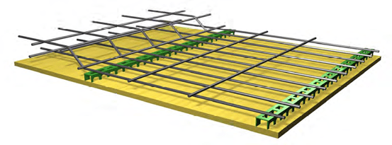
Ensuring the slab’ upper reinforcement position
The position of the upper (negative) slab reinforcement, either placed in the support between two slabs or in the support between a slab and a balcony (cantilever slab), can be secured only with the use of special rebar chairs.
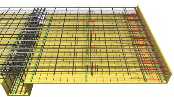
In the continuous slab with the cantilever, shown at the picture below, the upper reinforcement proper positioning is achieved by three ways:
- directly on the formwork with the use of rebar chairs
- indirectly with the use of folded mesh spacers
- indirectly with the use of S-shaped mesh spacers.

Direct, rebar chair.
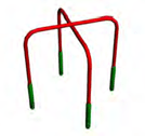 Prefabricated element, made out of a thin steel rebar with plastic tipped legs in order to prevent corrosion of the support area between the rebar chair and the formwork.
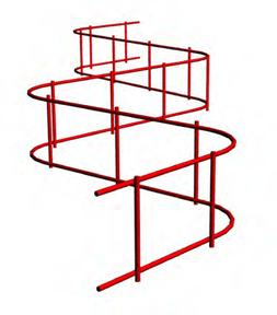
Indirect, S-shaped mesh spacer.
Prefabricated, comes in packages of straight lengths. It is formed in an S shape during the implementation.
Indirect, folded
mesh spacer.
It is easily formed by folding wire of a
standard density round Φ8/20, to the desirable height. In cases of cantilevers apart from spacer it can be used as “J- pin” reinforcement, necessary for the cohesion of the free edges.
Indirect “J-pin” rebar chair.
For sheer use in slabs’ free edges.


In cases where mesh is used as upper reinforcement in a slab support, its position can be se- cured with the use of an S-shaped mesh spacer placed on the lower reinforcement grate along the length of the plastic spacer.
In cases where support upper reinforcement comes from bend up span rebars, its proper placement is achieved by the reinforcement bending and therefore bar chairs might not be nec- essary.


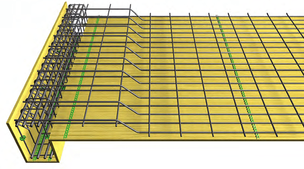
Two indirect S-shaped mesh spacers are placed to the left support of the continuous slab. These are fitted upon the lower reinforcement grate along the length of the linear plastic spac- ers.
Support of the negative slab’s reinforcement with rebar chairs and folded mesh spacersς
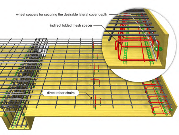
In the right support (cantilever balcony) of the above continuous slab, two rows of spacers are placed. The first row consists of indirect folded mesh spacers fitted upon two longitudinal plastic spacers and the second row consists of a number of direct rebar chairs.
It is mandatory to prevent the folded mesh spacer from lateral slipping and this can be achieved with the use of local spacers. They must be placed right after the implementation of the folded mesh spacer and prior to its wiring with the slabs’ reinforcement. When using wheel spacers extra attention should be paid to their vertical placement so as to avoid drifting during concret- ing. However when they are used in slab “foreheads” (as shown in the above figure) they can be horizontally placed since concrete does not fall directly upon these areas.

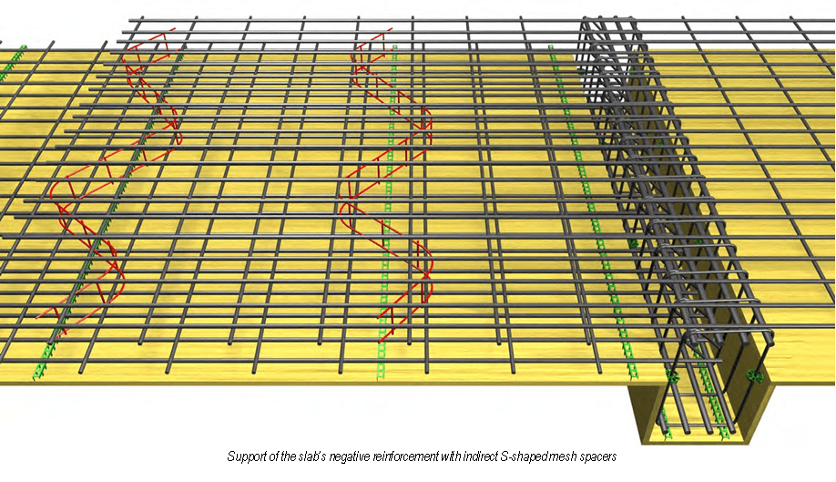
Support of the negative slab’s reinforcement with indirect S-shaped mesh spacers and folded mesh spacers
 Alternatively, when having a light-weight steel mesh as the lower reinforcement of a cantilever it is recommended to use indirect S-shaped mesh spacers instead of direct rebar chairs. In that case it is more practical to place a “J-pin” mesh spacer inside which the mesh will be properly sited.
Another solution, even when there is reinforcement mesh on the lower side of the slab or the cantilever, is the use of direct rebar chairs rather than indirect S-shaped mesh spacers.
Use of steel rebar chairs directly placed upon the formwork is strictly forbidden and furthermore the use of old type impromptu spacers is more expensive.
Beam reinforcement covering
The minimum required cover depth for beam rebars usually ranges between 2.5 and 3.5 cm de- pended on the environmental conditions present throughout the building’s service life. The 2.5 cm apply to a dry climate and the 3.5 cm to a seaside location.
Beam stirrups should be supported at the base of the beam, by a uniform inactive bar since all reinforcement loadings are transferred to these areas.
Lateral cover depths should be created with the use of special plastic spacers. When using stir- rup cage it is wiser to place the wheel spacers upon the connecting rebars in order to secure their position during concrete casting.
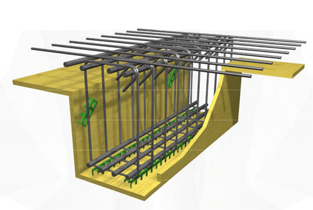
Lateral spacers do not bear any loads, therefore it not necessary for them to be heavy duty. Moreover they should be placed after the implementation of the stirrup cage inside the beam’s formwork and prior to the wiring of the beam’s rebars to the slabs reinforcement.
The use of lateral longitudinal plastic bars (like the ones placed at the bottom part of the beam) creates two problems: a) it does not enable the implementation of the stirrup cage inside the beam’s formwork and b) it obstructs the proper concrete casting of the beam. If the stirrup cage has been industrially producted, it will have secondary longitudinal connecting bars. In such a case, pieces of vertically fitted plastic bars may be used.
Column reinforcement covering
The minimum required cover depth for beam rebars usually ranges between 2.5 and 3.5 cm de- pended on the environmental conditions present throughout the building’s service life. The 2.5 cm apply to a dry climate and the 3.5 cm to a seaside location.
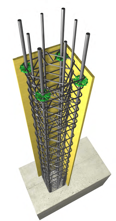
Forming the desirable covering of column reinforcement is quite a simple task. For example, four (4) individual spacers placed at the column’s upper part, are enough since the column’s base rebars are wired together in the lap-splice areas.
Especially for columns, the use of spacers for creating the re- quired cover depth helps in the proper centering of the vertical rebars. Therefore when the rein- forcement of the next storey is being placed no extra time (with a corresponding additional cost) will be spent in bringing the re- bars to their proper position.
Covering can be secured either with wheel spacers placed on the upper part of rebars (in that area there is no danger to be drifted during the concreting) or with the use of vertical wheel spacers fit- ted upon the stirrups or finally with the use of plastic pieces ver- tically positioned upon the form- work.
In every case though, spacers must be fitted after the position- ing of the stirrup cage in order to facilitate the implementation of the cage and the proper center- ing of rebars.
Shear wall reinforcement covering
As far as the integrated columns at the wall edges are concerned, the required cover depth is created as mentioned in the paragraph referring to the columns’ reinforcement covering. As far as the wall body reinforcement is concerned, its cover depth is created according to the follow- ing:
After forming the back of the wall, plastic rods are nailed upon the formwork. These rods have a usual length around 2.0 m and they can be used as one single piece or separate smaller piec- es.
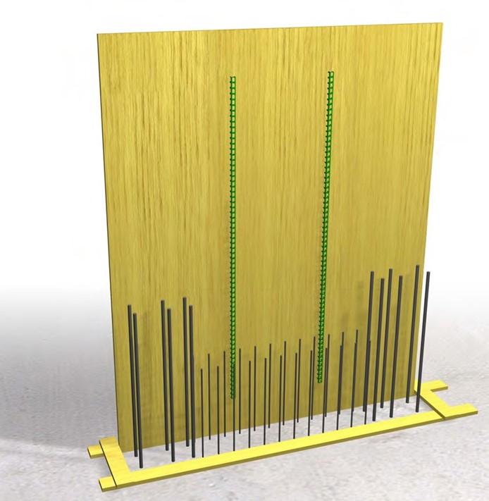
The two longitudinal spacers are nailed upon the formwork
After this, follows the implementation of the edge columns, of the body reinforcement and of the spacers that are fitted upon the internal reinforcement grate. That way after the placement of the formwork’s last piece the required cover depth and the proper centering of the reinforcement will be secured.
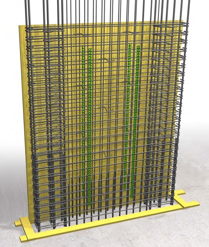
After the reinforcement implementation and prior to ‘closing’ the shear wall’s formwork, the two plastic bars are tied upon the inner reinforcement grate.
In shear walls the most effective way of the reinforcement implementation is to place the rein- forcement before the assembling of the formwork. In that case, spacers are fitted upon the re- bars.
Foundation reinforcement covering
The minimum required cover depth of the foundation reinforcement is around 4.0 cm for founda- tion “sited” on ground leveling slab and around 7.0 cm for foundation “sited” directly upon the ground.
The construction of foundation directly upon the ground’s surface is allowed only in special cas- es. The ground leveling slab ensures many things like:
- comfortable area to work on
- capability of accurate marking of the areas of footings and columns
- a stable substrate on top of which spacers will be placed
- avoidance of a muddy foundation ground due to water usage or possible rain
The required covering may be created by point or even better by linear spacers. Because of the weight they bear and due to their required height, it is recommended to use heavy duty spacers.
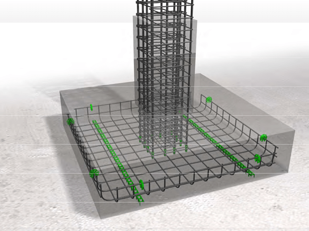
Securing the cover depth of the spread footing’s reinforcement with plastic spacers
Use of spacers on the sides of the footings is obligatory in order to prevent rebars from slipping. Since they do not bear weight, they can be sparsely placed and they should be fitted vertically to avoid drifting during the concreting process.
Ensuring the proper position of upper reinforcement in foundation slabs
In cases of total or partial raft foundation or when constructing the bottom slab of a pool, the use of rebar mesh as upper reinforcement is necessary.
Just like in superstructure slabs, in the areas around the slab edges, “J-pin” rebars may be combined with open or closed reinforcement mesh.
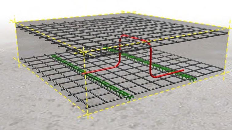 In the intermediate area, the required cover depth can be created with the use of special steel rebar chairs placed on top of the lower reinforcement grate.
The upper foundation grate is supported by steel spacers, which are sited upon the lower grate
Minimum spacing between reinforcement bars
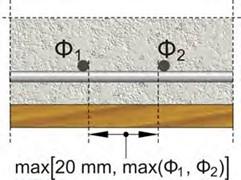
The distance among reinforcement bars must be such to allow the concrete’s gravel to pass be- tween them. In order to have properly anchored reinforcement, it is mandatory for rebars to be surrounded by concrete.
The minimum spacing between two reinforcement bars is the maximum of 25mm (or at least 20mm) and the diameter of the largest rebar. For instance, rebars with a diameter lesser or equal to Ø20 must have a minimum spacing of at least 20 mm and rebars larger than Ø20 must have a distance between them at least equal to their diameter.
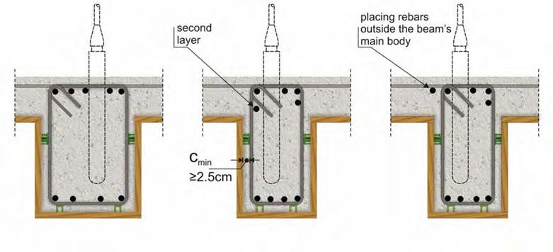
These spacing requirements are easily met in slabs and columns. However in beams extra at- tention must be paid mainly to the support and the joint areas.
The problem in beams is related to the concrete’s casting and it can be dealt with three different ways or in certain oc- casions with a combination of them.
For satisfactory results it is very important not only to use the vibrator in the proper way but also to avoid over- vibrating the concrete of the elements.
-
Large beam width b) Use of the second
layer, which is placed in contact with the stirrups.
c) By placing rebars on both
outer sides of the beam’s
main body.
It is allowed to place 25% of the total reinforcement outside the beam’s main body.
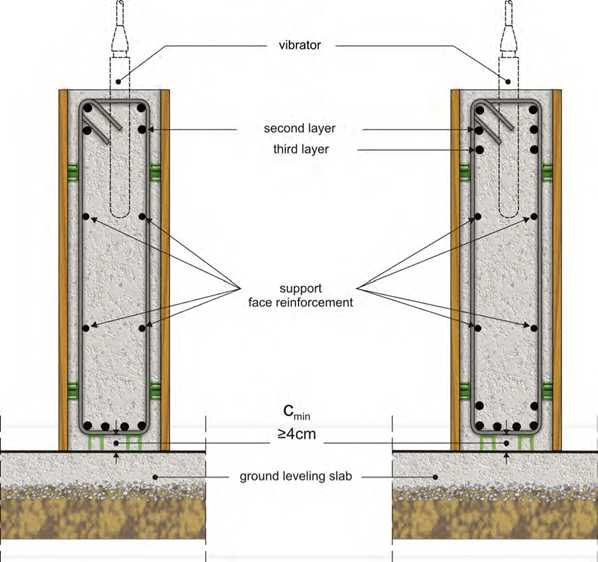
Connecting beams in foundation
Concrete casting in foundation connecting beams is not an easy procedure. These beams are not fixed together with a slab as are superstructure beams; consequently concrete has to be purred down the beam’s tight top opening and reach the bottom side.
Because of the fact that connecting beams normally have a large height as well as a large in- ternal lever, it is preferable to place rebars in two or even three layers along their height.
Rebar bending
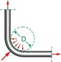 Reinforcement bars are being bent either in order to follow the stresses developed in the mem- ber or to get properly anchored.
The minimum diameter D (mandrel diameter) to which a bar is bent shall be such to avoid bending cracks to the bar and ensure the integriy of concrete inside the bent of the bar where large forces appear. The smaller the man- drel diameter is, the larger these forces are and conse- quently the concrete may fail thus leading to the disinte- gration of the cross-section.
Anchorage with bends and hooks
Anchorage is the extended length of a rebar inside the concrete in order to provide adequate adhesion between those two materials. That way when the steel receives forces, it will be able to reach its maximum strength capacity. Anchorage may be achieved by a straight bar or by a hook at the end of the rebar.
If the mandrel diameter of a bent-up bar is not the one required, there is danger of cracking thus losing a large amount of strength capacity. This will happen even if the cracks are not visible to the human eye.
Forming the right mandrel diameter has no additional cost since bending machines have appro- priate rings for changes in the rolls diameter.
Practically, the minimum bend diameters are:
- for slab rebars 4Ø,
-
for column or beam rebars anchored inside frame joints: (4 έως 5)Ø for rebars ≤ Ø 16,
(7 έως 8)Ø for rebars > Ø 16.

The mandrel diameter may be equal to 80mm and 160mm for Φ16 rebars and Φ20 rebars respectively
Anchorage with bend in a well confined joint
A well confined structural member is an element that has enough and properly placed stirrups both around and inside its perimeter. This is thoroughly presented in the chapter reffering to columns.
The minimum mandrel diameter is defined by various factors but a typi- cal value is around 15Ø. This me- thod of anchorage is preferred when there is no possibility to use large sized columns (like a column with one side <70cm).

Antiseismic stirrups
In the case of an earthquake, the most critical factor regarding the strength capacity of a struc- ture are the stirrups which should be produced and placed according to all antiseismic specifica- tions. For example, in the 7.9.1999 earthquake, in Attiki, no buildings would have had collapsed if their vertical reinforcement was the one required by today’s regulations and no serious dam- age would have been inflicted to 80% of the structures that presented severe problems in their structural frame.
Stirrups constitute one of the most crucial factors affecting the quality and the earthquake resis- tant strength of buildings.
Three are the major reliability parameters of stirrups:
-
The appropriate hooks at its free edges. Hooks are absolutely necessary for the proper behavior of stirrups especially during an intense seismic incident, when concrete spalling occurs, leaving hooks to be the only anchoring mechanism.
-
The mandrel diameter. Stirrups must be bend in rolls with a diameter at least equal to 4Ø, i.e. for Ø 10 they must have a diameter greater or equal to D = 40 mm.
-
The required distance between the legs of a closed stirrup. These must be placed at least 20 cm apart from one another (e.g. a column 50×50 must have three stirrups in each layer).
A column with 10% fewer rebars has around 10% lower capacity strength. However, if we re- move even a single intermediate stirrup, the capacity strength of that same column will be low- ered even by 50%. This happens because the stirrup’s removal doubles the buckling length of the rebars previously enclosed by it.
In a seismic event, columns always fail in the same way:
- When stirrups open, concrete disintegration in the column’s head or foot occurs.
-
Once the stirrups’ ends become apart, longitudinal reinforcement buckling and concrete disintegration take place.
That type of failure does not appear only to columns dimensioned according to old regulations and therefore have fewer rebars but also to newer columns with large amount of reinforcement, when they are not constructed according to the correct specifications:
- with internal and external stirrup adequacy,
- with correctly formed, antiseismic stirrups.
Throughout the world, structures collapse even when they have a large amount of reinforce- ment. The reason for this is always the same; lack of properly shaped and placed stirrups.
During a seismic event intense forces are applied to both concrete and rein- forcement bars. These forces cause the lateral enlargement of the former and the buckling of the latter up to the point of their fracture.
The earthquake resis- tance of beams and col- umns depends mainly upon their vertical rein- forcement. Stirrups en- sure the confinement of the rebars fitted inside them and the integrity of the concrete that tends to spall due to lateral enlargement. If stirrups are not properly an- chored they may open even in low intensity seismic events.
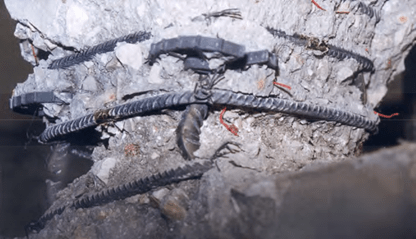
Typical failure of a column’s upper part.

Failure of a column dimensioned according to old regula- tions that required a peripheral stirrup with its end bent in 90° instead of 135° (45°).
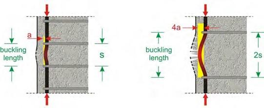
Generally column failure is induced by rebar buckling which leads to the fracture of longitudinal reinforcement. When there is adequate confinement, buckling length equals the distance be- tween the stirrups. However in cases of loose end stirrups (open stirrups), according to the Greek Code, buckling length may reach twice or three times the stirrups’ spacing in the critical duration of an earthquake.

Properly closed stirrup with a hook length equal to 100mm, bent in a 40 mm diameter roll (for stirrup bar Φ10)
Properly reinforced column 50×50 with 3 stirrups in each layer


