
Creating the Stairs, Reflected Ceiling Plans,
Furniture Plans, and Miscellaneous Plans
Starting the Tutorial
- Start Revit 2021 by clicking on the icon on the desktop.
- Open the last file from Tutorial Four, RL4-4.
- Save the file as RL5-1.
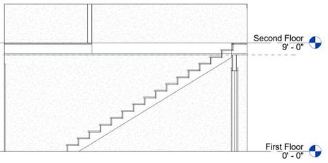
In this tutorial you will create the stair leading from the first to the second floor. You will then create the ceilings for the individual rooms and spaces on the first and second floors. From these elements you will then create Reflected Ceiling Plans for both floors. Once the ceilings are in place you will add lights. These lights will provide lighting for the rooms when the interior 3D views/renderings are created. In addition, Furniture Plans and other Miscellaneous Plans and Details will be created.
Creating the Stairs and Railings, Creating the Second Floor Opening
and Modifying the Wall Profile
In this part of the tutorial you create the stairs, add the floor openings for the stairwell, and modify the profile for the first floor wall next to stairs leading up to the second floor.
- Open the First Floor view.
Since you have added elements for the site plan, hide the categories for the property lines, trees, people and cars.
- Zoom in on the front entry area.
You will create stairs that start at the beginning of the left edge of the entry to the second floor.
Stair Beginning Point
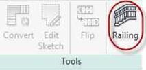
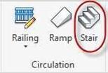 Click on the Stair tool in the Architecture tab, Circulation panel.
Stair Tool
- There are two methods to add stairs, Stair by Component and Stair by Sketch.
You will use the first method.
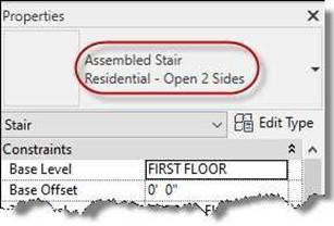
- Set the stair type to Assembled Stair Residential – Open 2 Sides.
-
Click on the Railing tool.
- Set the Railing Type to None. You will add the railing later.
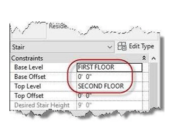
- The base should be set to First Floor and the Top Level set to Second Floor.
Railing Tool
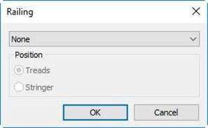
Railing Set to None
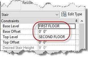
Stair Type and Level Settings
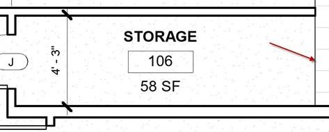
- Set the Location Line to Run: Left, Offset 0′ 0″, and the Actual Run Width to 4′ 3″.

Option Bar Settings
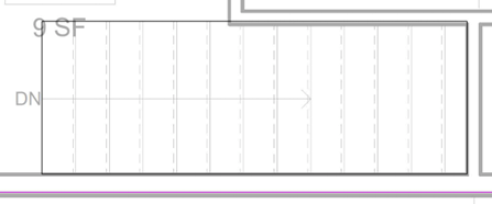
- Click at the point indicated; then drag the stair to the left.
Note the text that gives you the number of risers created and the number remaining.
Risers Created and Remaining
- Continue until it says 0 remaining.
 Click the mouse and then the Green Check. The stairs are created.
Stairs Created
-
Next you will create the opening for the stairwell on the second floor.
Open the Second Floor view.
-
Right-click on the floor and select Override Graphics in View, By Element…
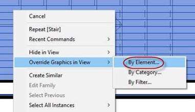
Override Graphic in View, By Element…
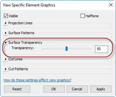
- Set the Surface Transparency to 50.
This will allow you to see the stairs below.
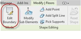
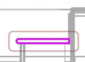
- Select the floor and click on the Edit Boundary tool.
You may have difficulty selecting the floor. If so, hide one of the exterior walls and click the floor edge.
- The edge of the floor will turn magenta.
Element Graphics Override
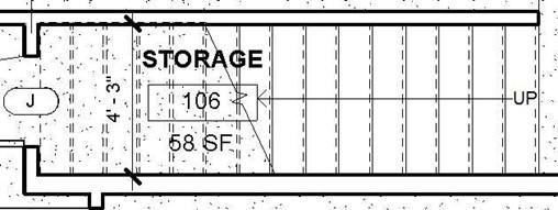
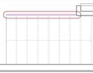
Draw a rectangular shape for the opening as shown.
Stair Opening Sketch
- Click the Green Check.
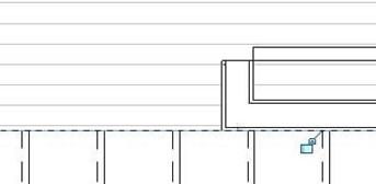
Click Attach button in the Alert Box.
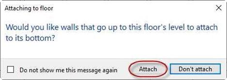
Alert Box
- If needed, align the location of the wall to the north of the stairs to match the edge of the stairs.
Also adjust the wall on the first floor.
Wall Aligned with Floor Opening
-
Select the floor and set the Surface Transparency back to zero. Checking the Vertical Clearance of the Stairs
Next you will check the vertical clearance for the stairs. The minimum clearance is
80″ (6′-8″).
- Open the First Floor view.
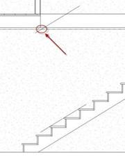
- Create an interior elevation view looking down towards the stairs.
- Click on the arrow portion of the elevation marker and move the front clip plane to the middle of the stair treads.
-
Open the view and crop to show the stairs and a portion of the second floor.
Interior Elevation View Added
Front Clip Plane Moved
- Draw a detail line from the tip of the tread nosing to the next tread.
Locate the line below the floor edge above,
-
Copy the line vertically 80″.
- The line will intersect the edge of the wall on the second floor.
Move the lines and the stair 11″ to the right. The line will now clear the wall.
Delete or hide the lines.
Note: Do not delete this view. You will need it later in the tutorial.
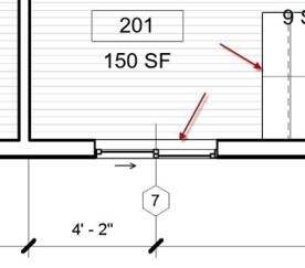
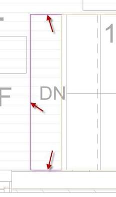
- Open the second floor view and adjust the opening in the floor.
Also move the window at the top of the stairs 1′-0″ to the left. This will allow for clearance for the end of the stair railing.
Note: If you are difficulty moving the window by changing the dimension, click on the window and then click the Activate Dimensions button in the Options Bar.
Line Added
Stairs Have Enough Clearance
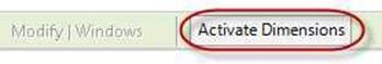
Activate Dimensions Button
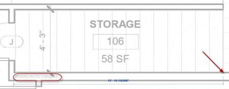
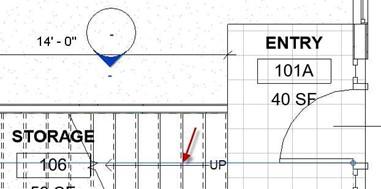
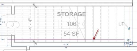
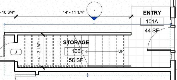
- Open the first floor view and adjust the boundary of the entry floor material.
Also adjust the room boundary by adding a room separator line at the first riser line and shortening the original line.
Opening and Window Moved
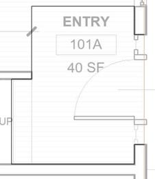
New Entry Boundary
- Open the interior elevation view of the stairs.
Name the view LIVING ROOM STAIRS – SOUTH.
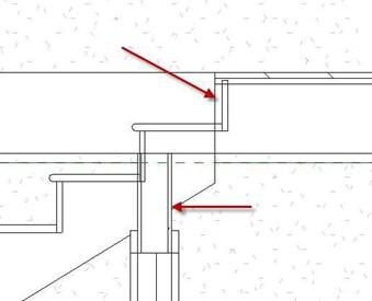
- You will see that the edge of the floor overlaps the top riser.
Also, there is no tread at the floor level and the wall on the first floor overlaps the stringer.
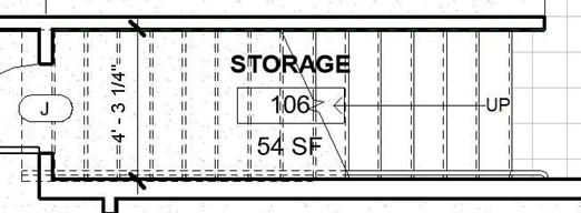
- To resolve these issues, you will do the following:
Move the left side of the floor opening 1 3/4″.
Align the wall on the first floor so that the left side is aligned to the edge of the floor.
Stair and Floor Connection Issues
Also attach the top of the wall to the bottom of the floor.
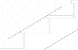
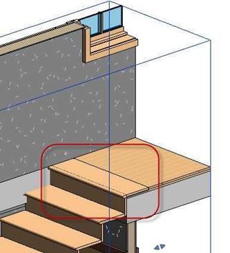
- The last thing that you will do is to create another tread that will be flush with the floor.
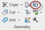
Click on the Component, Model In-Place tool.
Select Stairs as the Family Category. Name the family, Tread.
- Select Extrusion in the Forms panel.
When the Work Plane dialog opens, click OK to pick a plane.
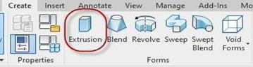
Extrusion Tool
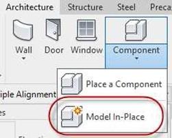
Component , Model In-Place Tool
- Choose the face of the stringer.
- To create the shape of the tread, use the pick lines option and choose the outline of the last tread.
- Move the tread to the next stair up.
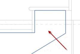
Pick this Face on the Stringer
Tread Outline Picked (Thick Line View Shown)
You will need to uncheck the Constrain checkbox to move the shape diagonally.

Constrain Checkbox
- Set the material of the tread to Cherry.
Click the Green Check twice to complete the process
Tread Moved
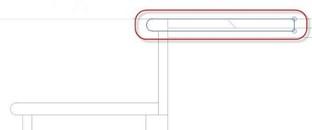
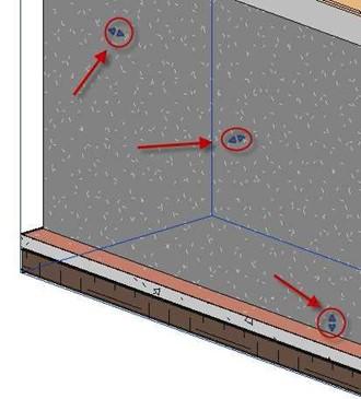
- Select the tread and switch to the second floor view.
Drag the top arrow so that the tread ends on the north side of the stairs.
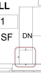
Drag Arrows
- The next thing is to use the Split Face tool to change the floor material at the tread.
The material will be Cherry.
- Click on the edge of the floor opening.
The edges of the floor and the opening will appear orange.
You will see a rectangular shape that is the edge of the tread.
- Click the three lines on the left side of the shape and the Click the Green Check mark to finish the shape.
- Click on the Paint tool and select Cherry as the material. Click inside the shape to paint the floor.
Split Face Tool
- There is an extra line for the edge of the floor.
Click on the Linework tool in the Modify tab, View panel and change the line to Invisible.
Invisible Line Selection Linework Tool
- Next you will set up a view to see the stairs as a 3D section view.
-
Select the stairs. We will use the stairs as the element to show in 3D.
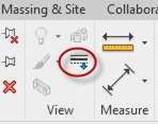
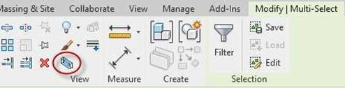
- In the Modify | Multi-Select contextual tab, View panel select the Selection Box tool.
This tool is only available if elements are selected.
Selection Box Tool
- After the tool is selected a 3D Section view will open showing the selected area.
The view is created in the Default 3D view.
Right click on the view in the Project Browser, duplicate it, and save the view as “Stairs – Section”.
Click on the section box around the edge and adjust the blue arrows to stretch the edges of the box.
Selected Elements in Section
Drag Control Arrows Tread Completed
Adding the Stair Railings
You will next add a railing at the second floor at the opening in the floor and a pipe rail on the south side of the stairwell.
- Open the Second Floor view.
Click on the Railing tool in the Circulation panel.
- Select the Railing Handrail – Rectangular railing type in the Properties Box.
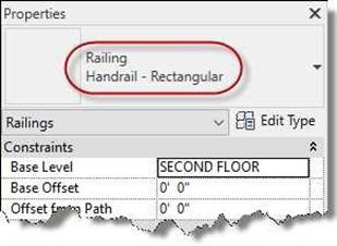
Railing Type Selected
- Draw the railing path as shown.
- Click the Green Check.
Position the railing so that it is on the edge of the floor opening.
 Railing Path Sketch
Railing Placed
- Next you will load a Newel Post to go at the end of the rail.
You will also load a pipe railing family for the south side of the stairwell.
- Open the Railing Samples.rvt file.
This file is included with the other support files downloaded from the website. It contains samples of various types of railings that may be used with the Revit program.
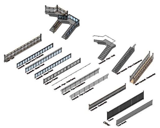
Railing Samples File
- Find the Handrail – Pipe – Wall Family in the Project Browser.
The family is located in the Railings, Railing folder.
First scroll down to the Families category and click the “+” sign to expand it, scroll down to Railings and expand it, and scroll down to Railing and expand it.
Right click on Handrail – Pipe – Wall and select Copy to Clipboard.
- Switch back to your project file.
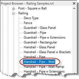
Handrail – Pipe – Wall Family
- Click on the Paste tool in the Modify tab, Clipboard panel.
- If the Duplicate Types alert box opens, click the OK button to accept it.
- The Handrail – Pipe – Wall family is now loaded.
-
Scroll up to the Post – Newel family and copy the
4 1/2″ family type to the clipboard.
Return to the project file and paste the family.
- Go to the Second Floor view.
- Click on the railing that you added earlier.
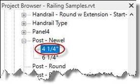
Post – Newel, 4 1/2″ Family
Click on the Edit Type button to open the Type Properties dialog.
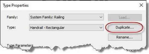
Duplicate Button
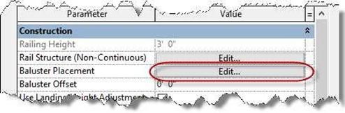 Name the new type: Handrail – Rectangular w/Newel Post. Click on the Edit… button next to Baluster Placement.
Edit… Button – Baluster Placement
- The Edit Baluster Placement dialog box opens.
The add the Newel Post, click in the Baluster Family field in the Posts area at the bottom.
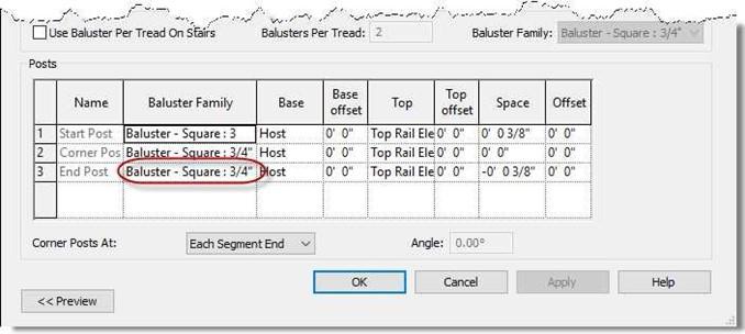
Baluster Family Field
-
Select the Post – Newel, 4 1/4″
Type.
The post will be placed at the end of the railing.
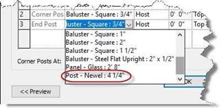
Post – Newel, 4 1/4″ Type Selected
- Open the 3D view used for the stairs to check the railing.
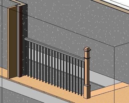
Newel Post Placed
Adding the Pipe Handrail to the Stairs
- Go to the First Floor view.
- Click on the Railing Tool.
- Select the Handrail – Pipe – Wall type.
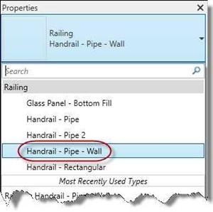
Handrail – Pipe – Wall Type
- Click on the Pick New Host tool.
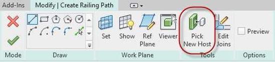
Pick New Host Tool
- Click on the stairs to set the host.
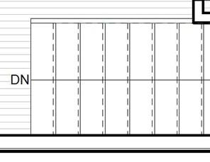
- Draw the path as shown.
Start the path at the first riser on the left and end at the last riser on the right.
Railing Path
- Click the Green Check to add the railing.
Completed Railing
- Open the Stairs – Section view.
- Rotate the view using the ViewCube tool the right, back side of the stairs.
The view will be oriented to the Right, Back orientation.
- Click on the edge of the section box.
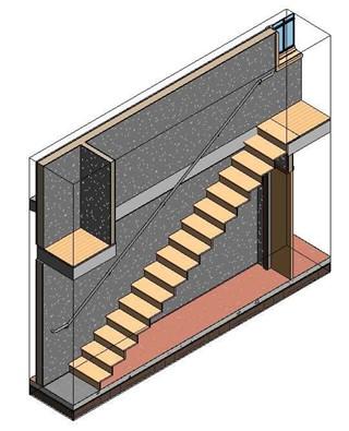 Use the Drag Control arrows to adjust the section box so that the stairs are sectioned down the middle and the full length of the railing is visible.
View Rotated and Section Box Adjusted
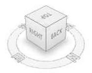
ViewCube
-
Next you will clean up the area where the walls and floor meet.
- First you will need to line up the face of the first and second floor walls.
 Rotate the 3D view to the Right orientation by clicking on the right face of the ViewCube.
ViewCube in Right Orientation
- Zoom in to where the first and second floor walls meet at the floor.
- Use the Align tool to line up the walls at the left and right sides.
Use the edge of the core for the alignment.
Also, click the first floor wall and attach it to the floor using the Attach Top/Base tool.
Align the pipe rail to the face of the wall.
Orbit the view back to a Right, Back orientation.
- Click on the Paint tool and select the Gypsum Wall Board material.
Paint the edge of the floor where it meets with the walls.
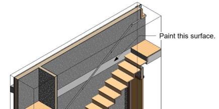
Edge of Floor to be Painted
Where Walls Meet Floor
Walls Aligned and Top of First Floor Wall Attached to Floor
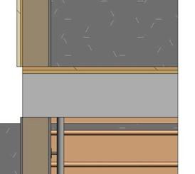
- The floor edge is now that same material as the two walls.
Surface Painted
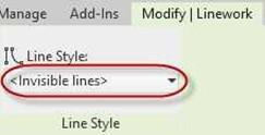
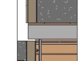
- Click on the Linework tool in the Modify ribbon, View panel.
- Select the Invisible Line Style and click the lines at the top and bottom of the walls. You will need to click the lines twice for each edge.
- The lines are now invisible.
This will make the wall surfaces appear as one wall.
 Note: The lines are only invisible in this view. The surface will be painted in all views.
Lines Changed to Invisible
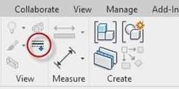
Linework Tool
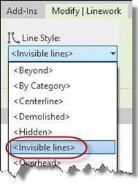
Invisible Lines Line Style
Modifying the Storage Room Wall and the North Stairwell Wall
The last thing is to modify the profile of the north wall of the stairwell. You will create a sloped edge at the base of the stairs on the first floor.
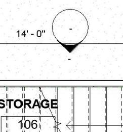
- Open the First Floor view and adjust the front clip plane ball to a point above the north stairwell wall.
Front Clip Plane Adjusted
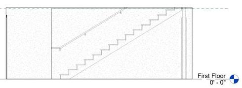
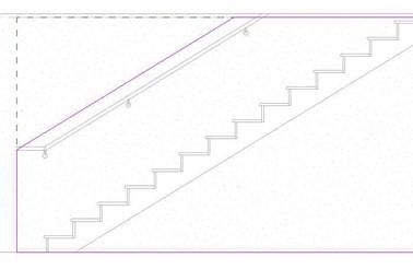
- Open the Interior Elevation of the south Living Room wall that was created earlier.
Adjust the crop window to clip the view to 8′-0″ above the first floor.
Elevation View of Stairwell
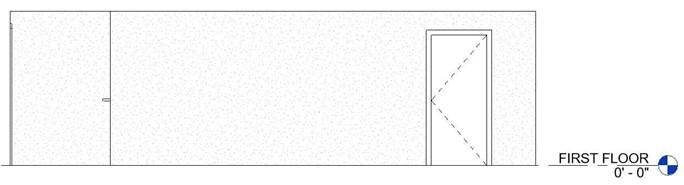
- Click on the wall and override the graphics so that the Transparency is set to 50.
Wall Set To 50 Transparency
- Click on the wall and then click on the Edit Profile tool.
- If the Alert Box opens, click Close to close the box.
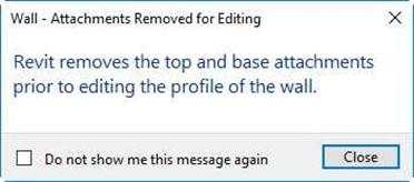
Alert Box
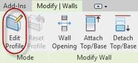
Edit Profile Tool
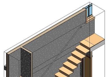
- Modify the wall to create a sloped edge that matches the slope of the stairs.
The top of the sloped surface will be 3′-6″ above the nosing of the stair.
- When drawing the sloped line, draw the line from one riser to another and then position the line on the tip of the nosing.
Note: You may need to estimate the position of the line. Make sure the angle matches the slope of the stairs.
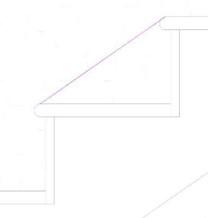
Step #1
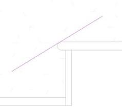
Step #2
- Move the line up 3′-6″ and trim to the vertical and horizontal lines.
Profile Sketch Completed
-
Change the wall back to a transparency of 0.
- Click the Green Check to complete the profile.
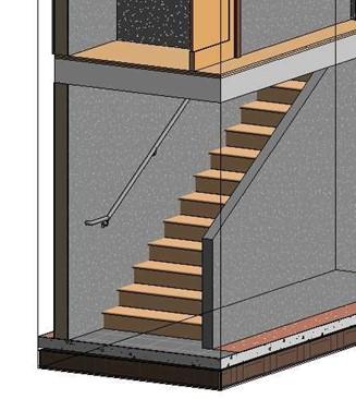
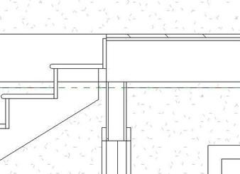
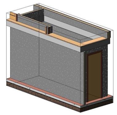
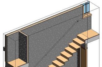
3D View of Modified Wall Profile
- This is the end of Part 1. Save your file as RL5-1.


