
Adding the Second Floor Interior Walls, Doors, and Windows
This part involves adding the second floor walls, doors, and windows. Some of the walls will need to be modified. By this time, you should have the first floor walls, doors, and windows located. Now you will need to lower the height of the interior walls to the correct height. This will be done in the 3D view.
- Open the RL1-3 file. Save the file as RL1-4.
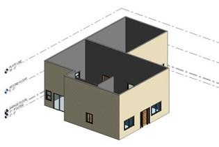
- Switch to the 3D view.
- To change the view to shaded color, pick on the small cube at the bottom left of the view and select Shaded.
Note: You may use the ViewCube tool to rotate the view. You can also hold down the middle mouse button and the Shift key to rotate the view.
- In the 3D view, you may see level markers to the side of the model. These can be repositioned to sides of the model in each of the views or they may be hidden.
For the book the level markers have been hidden. You should hide the level markers in the 3D view, they will not be needed.
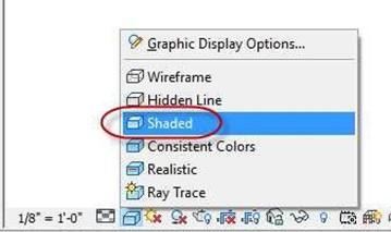 Shaded View Setting
Level Markers in the 3D View
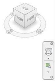
 ViewCube and
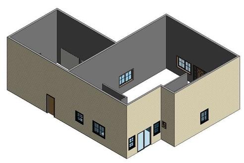
Navigation Bar 3D View of First Floor Walls
-
If some of the windows appear to be positioned too low, click on the window
and set the Head Height to 7′-0″.
- The tops of the walls are at 20′- 0″. Click on the exterior walls and change them to the Top Plate level in the Properties dialog box. This will lower the top of the walls to 18′-0″.
By holding the Ctrl key while clicking on the walls you can select multiple walls and change the heights at the same time.
- Switch to the First Floor view.
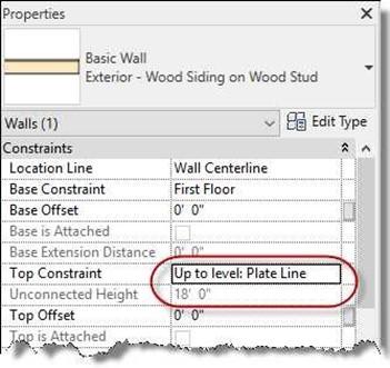
Top of Wall Set to Plate Line Level
- You will need to split the exterior wall on the west side of the building at the corner where the Garage and Kitchen meet. You will also need to split the wall on the east side at the opposite corner.
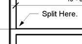
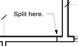
First Split Location Second Split Location
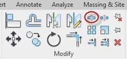
Split Tool
- Note: The reason for the split is so that you will have two separate wall types and will be able to lower the top of the garage walls separately.
- Select the three garage walls. Set the height to 9′-10″.
- Select the garage separation wall and set the height to Second Floor.
- Change the separation wall to the new type.
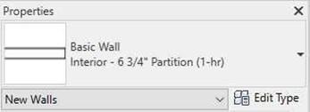
- Select the Interior – 6 3/4″ Partition (1-hr) wall style from the type selector.
Wall Type Selector
- Pick the Edit Type button to open the Type Properties dialog box.
Click the Preview>> button and then the View drop-down to show a section view of the wall preview.
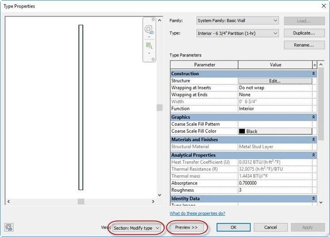
Type Properties Dialog Box
-
Click the Duplicate Button and name the wall: Interior – 7 1/4″ Garage
Partition (1-Hr).
- Click the Edit button next to Structure.
- Match the settings to the dialog box below.
Use the Insert button to add new layers to the wall. To change the material of the wall, click on the name of the material and click the small button to the right.
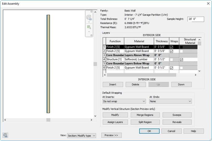
Edit Assembly Dialog Box
- Zoom in on the right side of the garage separation wall.
- Turn on the Thin Lines toggle in the Quick Access tool bar.
- If needed, use the Align tool in the Modify ribbon to align the top edge of the wall core as shown.
Select Faces of core in the options bar.
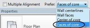
Faces of Core Option Selected
- Trim the corner of the two exterior walls and then move the endpoint of the garage wall until it touches the corner. The wall join should clean up automatically. You will also need to delete the small piece of wall to the left of the join.
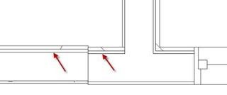
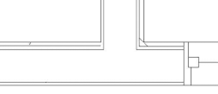
Before After
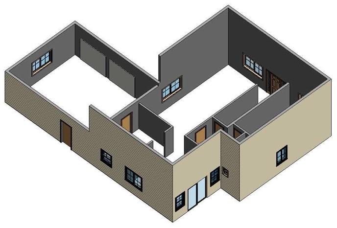
Garage and Interior Walls Lowered
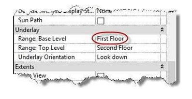
- Switch to the Second Floor view.
In the Properties for the view, set the Underlay Range: Base Level setting to First Floor.
Note: The underlay setting is used to show elements from another level on the current level. The underlay setting may already be set.
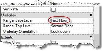
Underlay Setting
- Your view should look like this…
- Add in the Second Floor Walls.
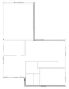
Second Floor View with Underlay Set to First Floor
All interior walls are Interior – 4 1/2″ Partition and the exterior walls are
Exterior – Wood Siding on Wood Stud.
Refer to the diagram for the location of the walls. Align the walls to the first floor walls where applicable.
- Add in the Second Floor Doors and Windows.
Refer to the charts for the second floor door and window types and sizes.
|
Window Number |
Window Type and Size |
Notes |
|
1 |
Window-Sliding-Double 72″ x 48″ |
Size is included. |
|
2 |
Window-Sliding-Double 36″ x 48″ |
Size is included. |
|
7 |
Window-Sliding-Double 48″ x 48″ |
Size is included. |
|
8 |
Window-Sliding-Double 36″ x 42″ |
This size has been created. |
|
Door Letter |
Door Type and Size |
Notes |
|
B |
Single-Flush 32″ x 80″ |
Size is included. |
|
D |
Sliding-Closet 72″ x 80″ |
Size is included. |
|
J |
Single-Flush 30″ x 80″ |
Size is included. |
Note: Use the Opening-Elliptical Arch 36″ x 84″ for the opening in the second floor bath. You will need to load this family from the BIMobject website (https://bimobject.com/) or from the Custom Families folder on the website. When loading the family use the Insert tab, Load Family tool. Use the Architecture, Component tool to place the family.
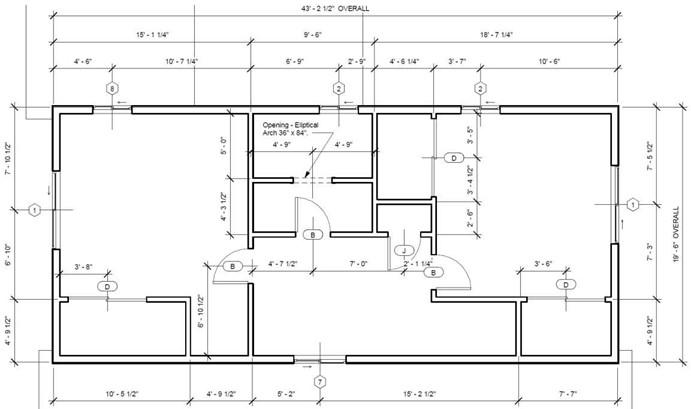
Second Floor Walls, Doors, and Windows
- Select the exterior walls (except for the three Garage Walls) and change the Top Constraint in the Properties box to the Plate Line level.
- Your 3D view should now look like this…
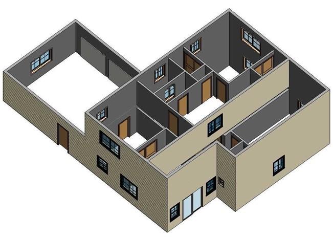
Second Floor Walls Added
- This is the end of Part 4. Save your file as RL1-4.


