
Adding the Dimensions, Sheet View, and Printing the Project
In this last part, you will add the remaining dimensions and other annotations to the drawing. You will also bring the view into a sheet view with a border.
- Open the WU3-2 file. Save the file as WU3-3.
-
Confirm that the scale of the view is set
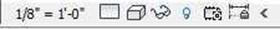
to 1/8″ = 1′-0″. The view scale selector is
at the bottom left corner of the view. View Scale
- Click on the Aligned Dimension tool in the Annotate tab, Dimension panel.
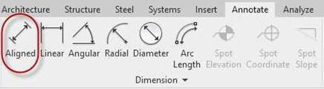
Aligned Dimension Tool
- Add the remaining dimensions to the plan view first. If you have already added all the dimensions, move on to the next step.
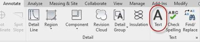
- To add the note for the roof overhang, click on the Text tool in the Annotate tab, Text panel.
- Click on the Two Segments tool in the contextual tab.
Text Tool
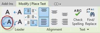 Two Segments Tool
- Click to place the arrow, click two more times to place the segments, and then type in the note for the text.
Use the Text 3/32″ Arial text type.
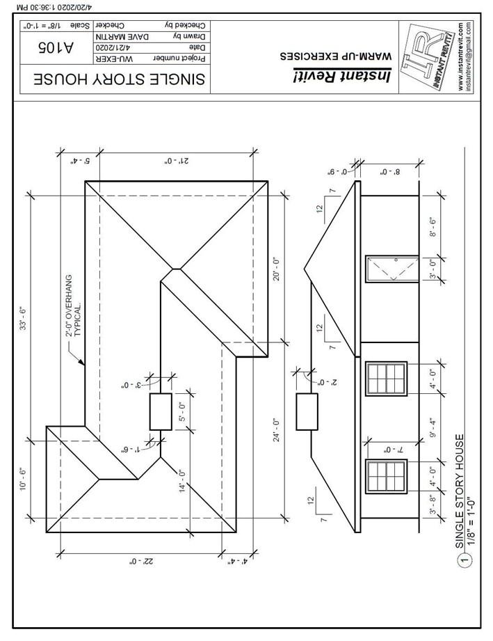
 Dimension the Front Elevation view.
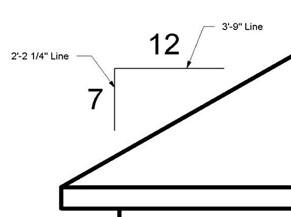
When creating the slope symbol, use the line tool and the text tool.
Note: The lengths of the two lines have been given to help create the symbol.
The vertical line is 2′-2 1/4″ and the horizontal line is 3′-9″.
Creating the Sheet View and Printing the Drawing
- The process to create the Sheet View is the same as with the other projects.
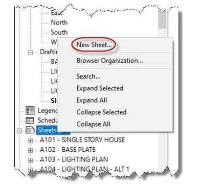
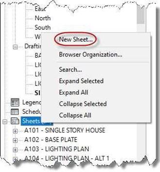
Begin by going to the View tab and selecting the Sheet tool in the Sheet Composition panel.
You may also right-click on the Sheets (all) text in the Project Browser and select New Sheet…
Slope Symbol Dimensions
-
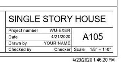
Open the sheet view and fill out the title block based on the example.
New Sheet… Option
 Click on the Print tool and print the drawing using the PDF redirect v2 driver. The scale will be Letter size paper, Centered, and Zoom 100%.
- Save the file to your PDF folder.
- This is the end of Part 3 and Warm-Up Exercise #3. Save your file as WU3-3.


Backup Files
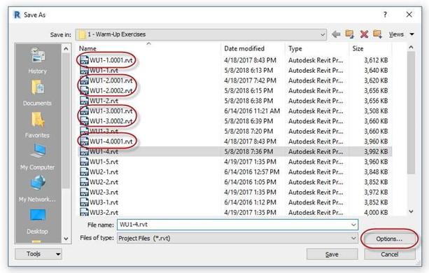
You may have noticed as you have progressed through the tutorials, extra files with the text 0001, 0002, etc. after the file name have been added. These are backup files of your original drawing.
By default, three backups are saved and are sequential. The setting to change the
number of files saved is in the Save As dialog box. Click on the Options… button.
After you have completed each tutorial, you may wish to delete the backup files to save space.
Save As Dialog Box
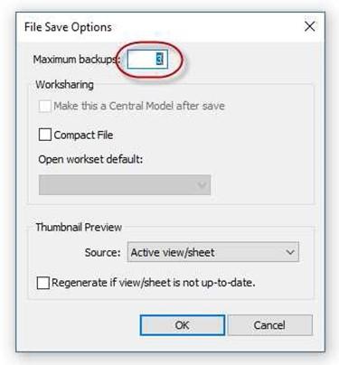
File Save Options Dialog Box


