
TYPES OF CIVIL ENGINEERING DRAWINGS
1. Proposal drawing or proposal sketching
2. Perspective
3. Submission drawing
4. Working drawings
5. Completion drawing
Proposal And Perspective
First architect collects data and requirements for the building such as the funds
available, plot size, use of the building, number of stories desired, north direction,
plot- level especially in comparison with road level, required room sizes, etc. Then he
makes a number of proposals keeping in mind the by-laws of the controlling authorities.
For proposals, plans and elevation are drawn on a very small scale like 1/8 or 1/16
while the section is usually not needed. Plans and elevation, in these drawings, are
made attractive even by colouring and, if needed, perspectives are also drawn to impress the client.
The proposals are then discussed with the client and changes are made according to his
wishes. Sometimes, if the client dislikes the proposals altogether, new proposals are to
be made. Offering of proposals is continued till the client is satisfied with a certain
plan.
Submission Drawing
Submission drawings are actually legal documents used to approve the plan from the
controlling authorities like LDA and LMC.
Plans (ground floor plan, first floor plan and so on), an elevation and a section is
drawn in these drawings. Plans are most commonly drawn on 1/8 scale. Section here
is used to give important heights but all the details are not required. That is why it is
also drawn on 1/8 scale and is taken through such a portion so that it is the simplest
sectional view.
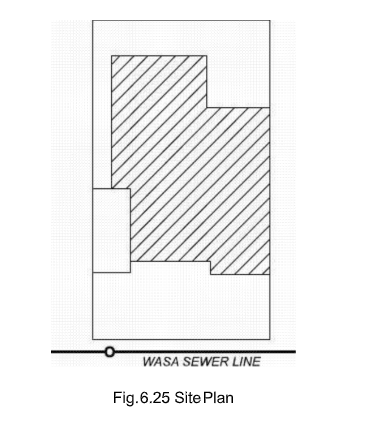
Site plan is required in the submission drawings for plots greater in size than 10
marlas. Site plan shows the block of actual building or the constructed portion as
compared to the total plot area. It is drawn on a very small scale like 1/16 or 1/32. If site plan is included in the drawing, the main plans are only drawn for the constructed
portion without showing the open spaces and the boundary wall. Various services are
also shown in the site plan, for example, if sewerage line is passing, two or three
man-holes of the main line are shown and then connection for the plot is indicated.
Further comments are written like “Disposal to WASA Sewerage Line” etc.
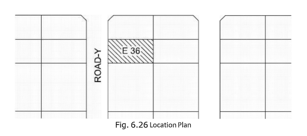
Location plan is also drawn to indicate the location of the plot, on a scale like 1/64. It is a part-plan of the total scheme; one or two main roads with their names and
neighboring plots are shown.
Doors, windows and ventilators are marked by D1, D2 . . . . . , W1, W2 . . . . . , and V1,
V2 . . . . . in the plans. The sizes of these components and other related details are
given in the form of a table called Schedule of Openings.
Statement of Areas or Schedule of Areas is also prepared in tabular form in which total
area of the plot, covered area, allowable covered area, ground floor covered area and first floor, covered area etc. are given.
Submission drawing should have the name and complete address of the owner and further it should be properly signed by the owner. The drawing should also be signed by a licensed architect. Sometimes stability certificate is also required.
These drawings are submitted to the controlling authorities and only after their approval, the
construction can be started.
Working Drawings
Working drawings are those drawings which are used for carrying out construction at the site
according to the design. Examples of the working drawings are as follows:
a) Architectural working drawings b)
Structural working drawings
i) Foundation plan
ii) Reinforcement details
iii) Plumbing works (Plumbing means he water supply and its disposal inside the
building)
iv) Details of doors and windows
v) Bathroom and kitchen details
vi) Electrification plan
After approval of the plan, through the submission drawing, architectural working
drawings are made in which all the details are given which are necessary for the at- site
construction. The sections are drawn on enlarged scales and as many number of sections are used as needed to clearly explain the structure. On blown-up scales, stair details and details of kitchen and bathrooms etc. are also shown. Further, position of various types of furnitures is also indicated in the plans. More than one elevations are drawn to represent the shape from different directions.
In working drawings, we can make small changes from the approved plans like
alteration in the position of doors and windows and small adjustments in the internal
sizes of the rooms.
After structural and plumbing design of the building, working drawings are made to
show the results of these designs.
Completion Drawing
After construction of the building, drawings are made according to the actually
constructed features called completion or as-built drawings. These drawings are then
submitted ;to the authorities to get the completion certificate and only after their
approval the owner can legally occupy the building.


