INTERSECTION OF SURFACES
While making orthographic drawings, the intersections between the various types of
surfaces are to be shown by certain lines. For example, when two planes intersect, a
straight intersection line is obtained.
Intersection of surfaces especially means the complicated lines obtained when
geometric shapes such as planes, cylinders, prisms, pyramids and cones intersect
each other.
Intersection of Two Cylinders at Right Angles
a) One cylinder is assumed horizontal – while the other vertical and three orthographic
views are drawn leaving the intersection line, as shown in Fig. 7.7(A).
b) Frontal cutting planes 1,2,3, and 4, etc. are assumed parallel to the axes of both the
cylinders as shown in the top view. The isometric view after cutting with plane-2 is
shown in Fig. 7.7(B).
The intersection points of this plane with the smaller cylinder, 2.1 and 2.2, can easily be
located in the top view and the isometric view. These points will be included in the
final intersection curve a is clear from the isometric view.
c) The assumed cutting planes are projected from the top view to the end view
through a 45° line. The points of intersection with the horizontal cylinder will be the
points of the intersection curve.
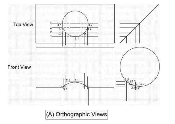
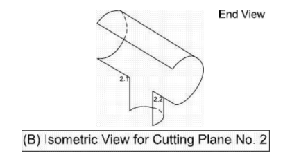
Fig. 7.7 Intersection of Two Cylinders
d) The points of intersection are projected horizontally and vertically from the end
view and the top view respectively to locate the intersection points in the front view.
e) The points obtained are then joined by a smooth curve which will be the required
intersection curve between the two cylinders.
Intersection of a Cylinder and a Right Cone
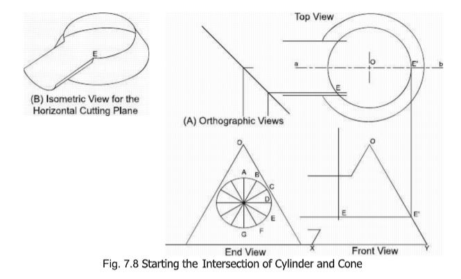
Three views of the cone and the cylinder are drawn first as shown in Fig. 7.8(P). The
cylinder in the E.V. is then divided into any number of equal parts, twelve in this case. The points A,B,C,D,E,F and G in the figure show the points of intersection of the cylinder
with the cone as seen from the end.
Each point is separately considered and is located in the other two views. To locate
point-E in the top and the front views, a horizontal cutting through point-E is
assumed removing the upper part as shown in Fig. 7.8(8).

Horizontal line at the height of the point-E is drawn in the front view showing the
horizontal cutting. Point-E thus obtained in the front view is projected to the top
view to intersect the center-line ‘ab’ . A circle is drawn passing through this point with
center at in the top view, showing the top edge of the frustum of the cone left after
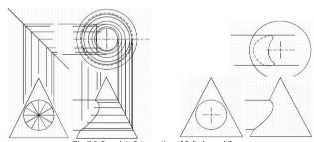
Fig. 7.9 Complete Intersection of Cylinder and Cone
a horizontal cutting containing the point-E. The point-E is now projected from the end
view to the top view to locate it there which is then projected vertically to the front
view to determine the same point in this view. All the points are located one by one
using a similar procedure and smooth curves are then drawn to represent the curves
of intersection.


