
DEVELOPMENT OF SURFACES
When a curved surface is unfolded to a single plane, the resulting figure is called
development of that surface. By using these surface developments a pattern layout
of any object can be constructed on some plane sheet which may then be used to
form the required shape.
Application of surface developments are found in metal sheet, plastic sheet and
paper sheet fabrications.
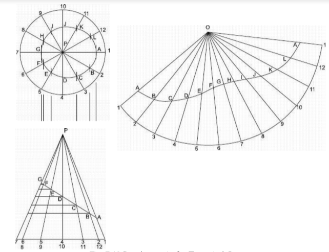
7.4.1 Development of a Truncated Right Circular Cone
a) Top view and front views of the cone are drawn first and the truncating line is
shown in the front view.
Fig. 7.10 Development of a Truncated Cone
b) The base of the cone in the top view is divided into a sufficient number of equal
parts so that the sum of the resulting chordal distances closely approximate the
periphery of the base.
In Fig. 7.10 the base is divided into 12 equal parts by drawing lines at 30°, 60° and 90°
angles form the central point. The points on the circle are numbered as shown in the
figure.
c) The points on the base are then projected down to the front view and are then
extended to the apex of the cone. The points of intersection with the truncating line are
named by capital alphabets A, B, C, D, E, F and G as shown.
d) The points A to G are then projected to the top view to meet the corresponding
elements. The points thus obtained are joined with a regular curve to form the top
view of the truncating part.
e) From a separate center ‘0’ , a curve is drawn with radius equal to the slant height s,
P-1 in the F.V., showing the true length of all the elements. This curve is called
STRETCHOUT LINE.
f) The chordal divisions of the base obtained from the T.V. are then laid off on the
stretchout line. Alternately, instead of finding true circumference of the base, the
angle 1-0-1 in the development may be set off equal to r/s x 360 °, where r’ is the
radius of the base and s’ is the slant height of the cone.
The stretchout may now be divided into the same number of equal parts as in the T.V.
making trials with the divider.
g) To obtain the true lengths of the elements for the development 1-A, 2-B, 3-C, etc.,
horizontal lines are projected from the points on the truncating line in the F.V. to any of
the slant side.
Compass is then set from point-P to each of these points in the F.V. and arcs are
drawn from point-C on the development to intersect the corresponding elements.
h) The points obtained on the development are then connected by a smooth curve. The
shaded part will then be the required development of the truncated cone.
This development can be separated by cutting it from the sheet and the Left and the
Right lines A-1 can be joined together by the tape. This will be a physical check for the
accuracy of the development.
Development of a Square Right Pyramid
a) Top view and front view of the pyramid are drawn according to the required dimensions.
b) The pyramid is assumed to be enclosed within a cone having the same vertex and
whose base is passing through the corners of the pyramid. This cone is shown in the two views by construction lines.
c) Development for the assumed cone is drawn and the four corners of the pyramid are
shown on it as elements of the cone.
d) The points representing the base corners of the pyramid are joined by straight
lines in the development to get the pattern layout for the pyramid.
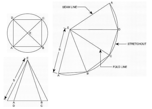
Fig. 7.11 Development of a Pyramid


