Inserting Blocks
After creating a block, you can insert it at the desired location inside the drawing using the INSERT
command. The procedures to insert blocks are explained in following examples.
Example:
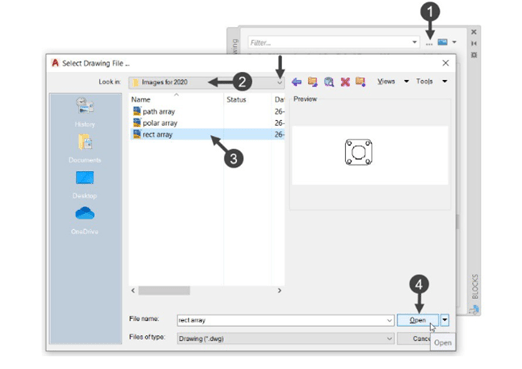
Click View > Palettes > Blocks from the ribbon to display the BLOCKS dialog box, as shown.
Next, select the block and drag the cursor to place it in the drawing area, as shown.
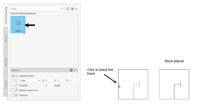
the block. You can either place the block using the mouse or by entering the required coordinates in
their respective edit boxes on the right side, as shown. If the checkbox is selected, the system will
define previously applied coordinates.
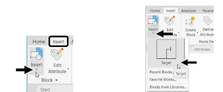
Note: You can also insert a block by clicking on the block displayed after clicking on the Insert >
Block > Insert from the Ribbon, as shown. This will be only available if you open it in the same
drawing file. Various tabs of this dialog box are discussed below:
Current Drawing – This tab displays the blocks that you create in the current drawing.
Recent – This tab displays the block that you created and inserted recently in the current & other
drawings.
Favourites – This tab displays preview of favourite blocks that were copied from other tabs of
the dialog box.
Libraries – This tab is used to display the blocks that you created in different drawings by
browsing and importing them, as shown.
Note: You can also insert a block by clicking on the block displayed after clicking on the Insert >
Block > Insert from the Ribbon, as shown. This will be only available if you open it in the same
Example (Scaling the block):
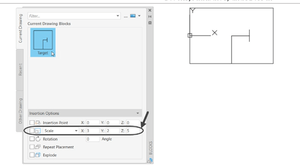
Activate the Block tool to display the BLOCKS dialog box, as discussed above.
Enter the required scale values in the X, Y, and Z edit boxes of the BLOCKS dialog box, as shown.
Next double click on the block displayed in the dialog box and click to place the scaled
block in the drawing area, as shown.
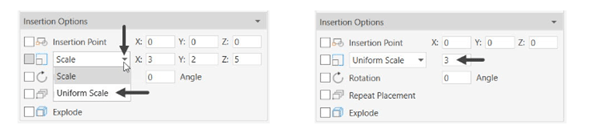
You can also scale the block with uniform distance by selecting the Uniform option, as shown. And
by selecting the check box on its left, the system will scale the block with default scale value.
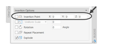
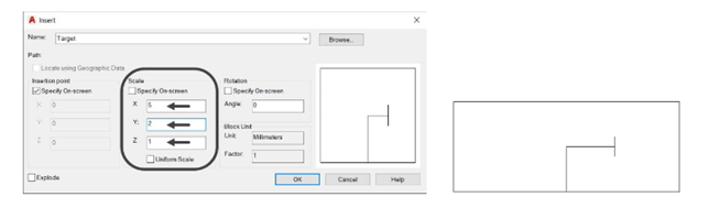
You can also scale the block by enter the CLASSICINSERT in the Command Bar to display the
Insert dialog box. And then enter the required scale value in their respective boxes and place the
scaled block anywhere in the drawing area, as shown.
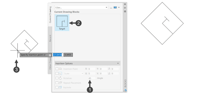
Example (Rotating the block):
Activate the Block tool to display the BLOCKS dialog box.
Enter the required rotation angle values in its respective edit box of the BLOCKS dialog box, as
shown.
Next click on the block displayed in the dialog box and click in the drawing area to place the
block with angle value entered, as shown.
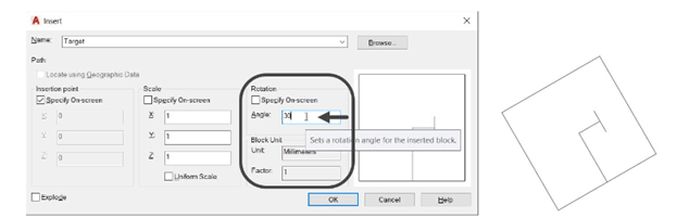
You can also rotate the block by enter the CLASSICINSERT in the Command Bar to display the
Insert dialog box. And then enter the required rotation angle value in the respective edit box and
place the block in the drawing area with angle value entered, as shown.
 Save and close the drawing file.
Creating Annotative Blocks
Annotative blocks possess the annotative properties. They will be scaled automatically depending
upon the scale of the drawing sheet. The procedure to create and insert annotative blocks is
explained in the following example.
Example:
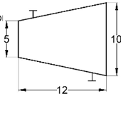
Start a new drawing file.
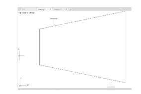
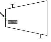
Create the drawing a shown in figure. Assume the missing dimensions.
Click Insert > Block Definition > Create Block on the ribbon;
the Block Definition dialog box appears.
Enter Turbine Driver in the Name field.
Click the Select Objects button on the dialog box. Drag a
window and select all the objects of the drawing. Right-click to
accept the selection.
Select the Delete option under the Objects section, if it is not selected.
Click the Pick Point button and select the midpoint of the left
vertical line, as shown.
Select the Annotative check box under the Behavior section of
the dialog box. Click the OK button on the dialog box.
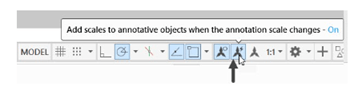
Activate the button located at the right-side of the Status Bar, as
shown.
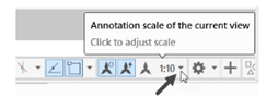
Set the Annotation Scale to 1:10.
Activate the Block tool to display the BLOCKS dialog box, as discussed earlier in this chapter.
Select the Turbine Driver block from the dialog box to display the preview of block with
scale factor 1:10, as shown.
Click in the drawing area to place it.
Click Zoom All on the Navigation Bar to view the block.
Change the Annotation Scale to 1:2; you will notice that the block is automatically scaled
to 1:2, as shown.