Freehand Sketch
PROJECTION METHOD
Perspective
Parallel
Oblique
Orthographic
Axonometric
Multiview
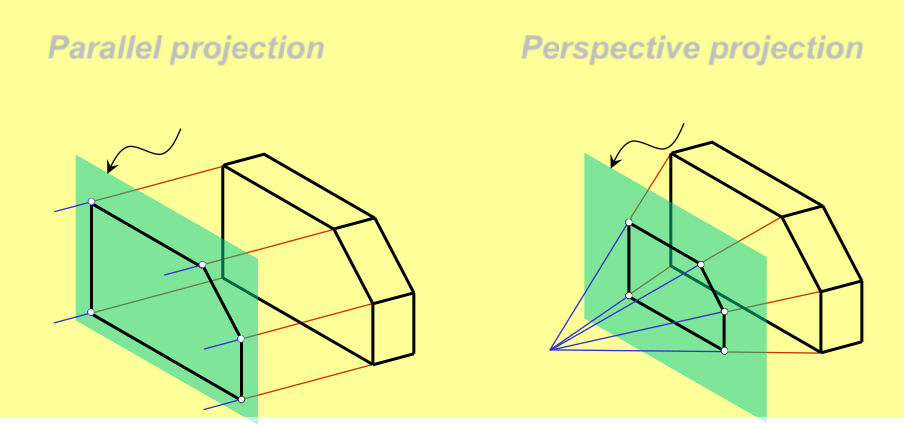
PROJECTION THEORY

 The projection theory is based on two variables:
- Line of sight
- Plane of projection (image plane or picture plane)
Line of sight is an imaginary ray of light between an observer’s eye and an object.

There are 2 types of LOS : parallel
and
converge
Parallel projection
Perspective projection
Line of sight
Line of sight
Plane of projection is an imaginary flat plane which
the image is created.
 The image is produced by connecting the points where the LOS pierce the projection plane.
Parallel projection Perspective projection
Plane of projection Plane of projection
Disadvantage of Perspective Projection

Width is distorted
 Perspective projection is not
used by engineer for manu- facturing of parts, because
- It is difficult to create.
-
It does not reveal exact shape and size.
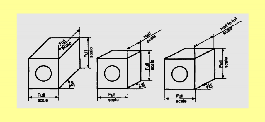
Oblique projection of an object may be obtained by
projecting the object with parallel projections.
- In oblique projection, the front face of the object appears in its true size and shape, as it is placed parallel to the picture plane.
Orthographic Projection
Orthographic projection is a parallel projection technique in which the parallel lines of sight are perpendicular to the projection plane MEANING
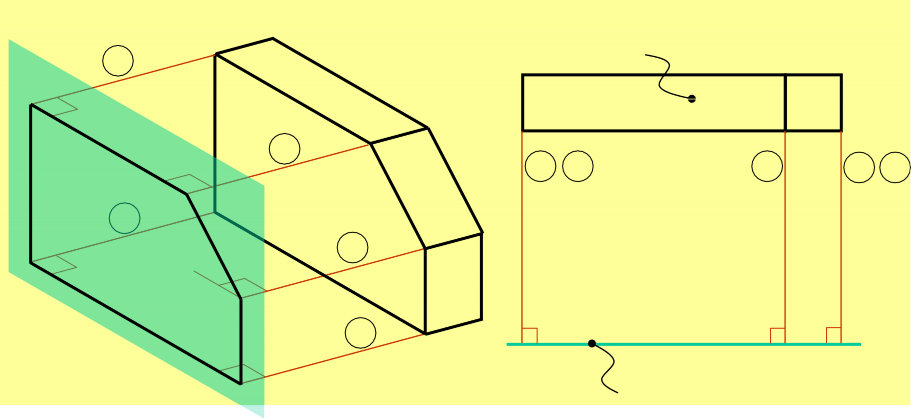
Object views from top
ORTHOGRAPHIC VIEW
Orthographic view depends on relative position of the object
to the line of sight.
More than one view is needed to represent the object.
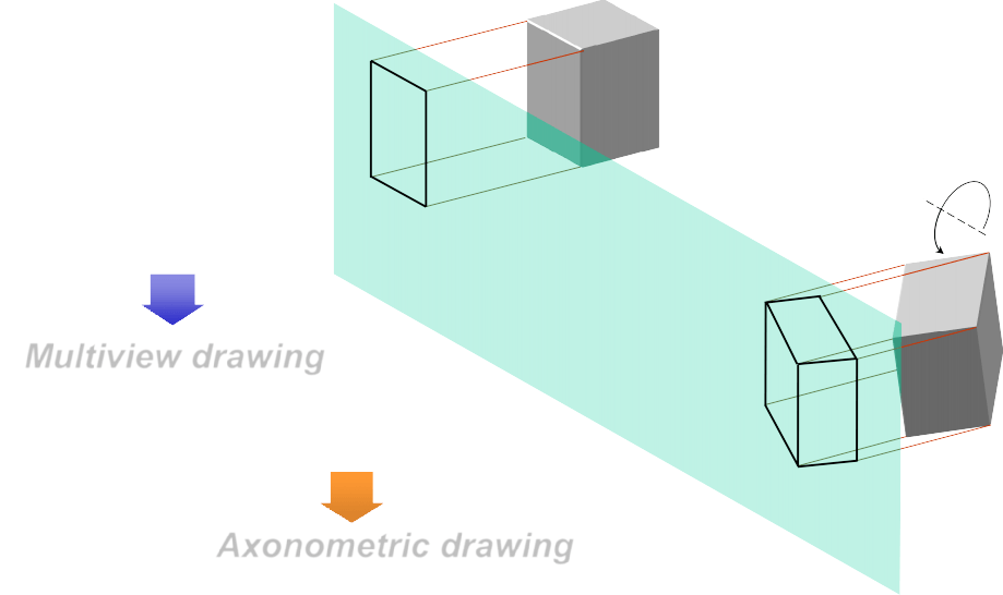
Multiview drawing
Three dimensions of an object is shown.
Axonometric drawing ORTHOGRAPHIC VIEW
NOTES
Multiview drawing
Orthographic projection technique can produce either
Axonometric drawing
that show all three dimensions of an object in one view.
Both drawing types are used in technical drawing for communication.
Axonometric (Isometric) Drawing
Advantage
Easy to understand
Disadvantage
Shape and angle distortion
Example
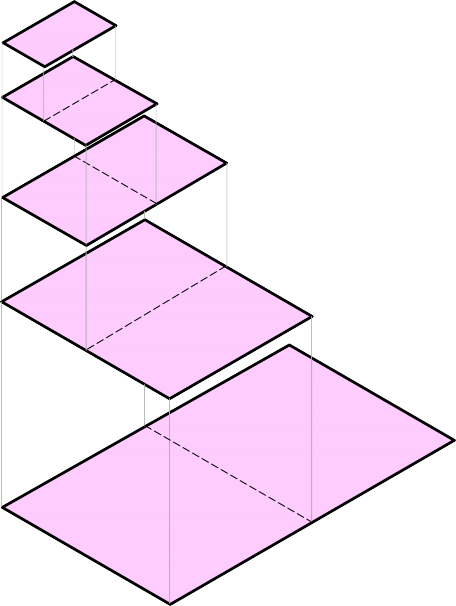
Distortions of shape and size in isometric drawing
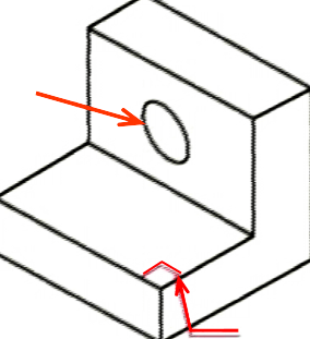
Circular hole becomes ellipse.
Right angle becomes obtuse angle.
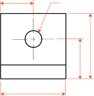
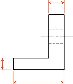
Multiview Drawing
Advantage
It represents accurate shape and size.
Disadvantage
Require practice in writing and reading.
Example
Multiviews drawing (2-view drawing)
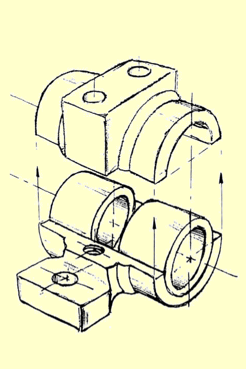
Freehand Sketching
Straight Line
-
Hold the pencil naturally.
-
Spot the beginning and end points.
- Swing the pencil back and forth between the points, barely touching the paper until the direction is clearly established.
-
Draw the line firmly with a free and easy wrist-and-arm motion

Horizontal line Vertical line


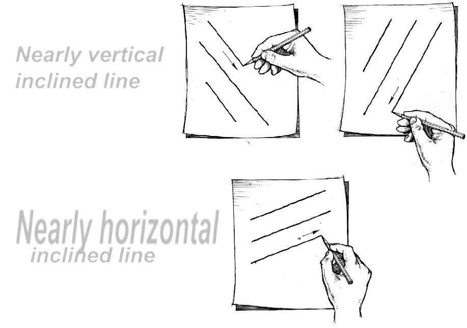
Nearly vertical inclined line
Nearly horizontal inclined line
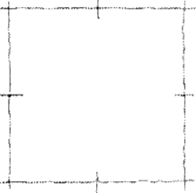
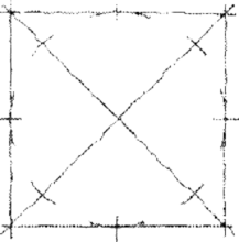
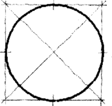
Small Circle
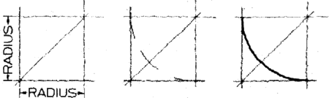
Method 1 : Starting with a square
- Lightly sketching the square and marking the mid-points.
- Draw light diagonals and mark the estimated radius.
- Draw the circle through the eight points.
- Lightly sketching the square and marking the mid-points.
Step 1 Step 2 Step 3
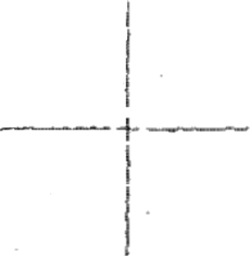
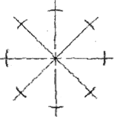
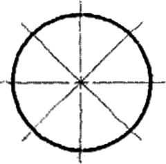
Small Circle
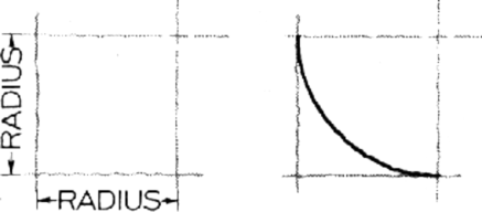
Method 2 : Starting with center line
- Lightly draw a center line.
- Add light radial lines and mark the estimated radius.
- Sketch the full circle.
Step 1 Step 2 Step 3
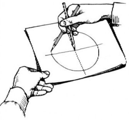
Large Circle
- Place the little finger (or pencil’ s tip) at the center as a pivot, and set the pencil point at the radius-distance from the center.
-
Hold the hand in this position and rotate the paper.

Method 1 : Starting with a square
Method 2 : Starting with a center line
Steps in Sketching
- Block in main shape.
- Locate the features.
- Sketch arcs and circles.
- Sketch lines.
- Block in main shape.
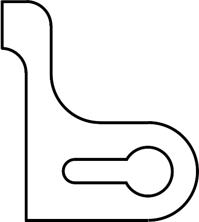
Example

Drawing Standard
Standards are set of rules that govern how technical drawings are represented.
Introduction
 Drawing standards are used so that drawings convey the same meaning to everyone who reads them.
Partial List of Drawing Standards
| Code number |
Contents |
| JIS Z 8311 | Sizes and Format of Drawings |
| JIS Z 8312 | Line Conventions |
| JIS Z 8313 | Lettering |
| JIS Z 8314 | Scales |
| JIS Z 8315 | Projection methods |
| JIS Z 8316 | Presentation of Views and Sections |
| JIS Z 8317 | Dimensioning |
Drawing Sheet
Trimmed paper of
a size A0 ~ A4.
 Standard sheet size
(JIS) A2
A4 210 x 297
A3 297 x 420 A1
A2 420 x 594
A1 594 x 841
A0 841 x 1189
(Dimensions in millimeters) A0
 Orientation of drawing sheet
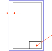
| Sheet size | c (min) | d (min) |
| A4 |
10 |
25 |
| A3 |
10 |
25 |
| A2 |
10 |
25 |
| A1 |
20 |
25 |
| A0 |
20 |
25 |
Drawing Scales
Scale is the ratio of the linear dimension of an element of an object shown in the drawing to the real linear dimension of the same element of the object.
Size in drawing Actual size
Drawing Scales
Designation of a scale consists of the word “SCALE“
followed by the indication of its ratio, as follow
SCALE 1:1 for full size
SCALE X:1 for enlargement scales (X > 1) SCALE 1:X for reduction scales (X > 1)
 Dimension numbers shown in the drawing are correspond to “true size” of the object and they are independent of the scale used in creating that drawing.
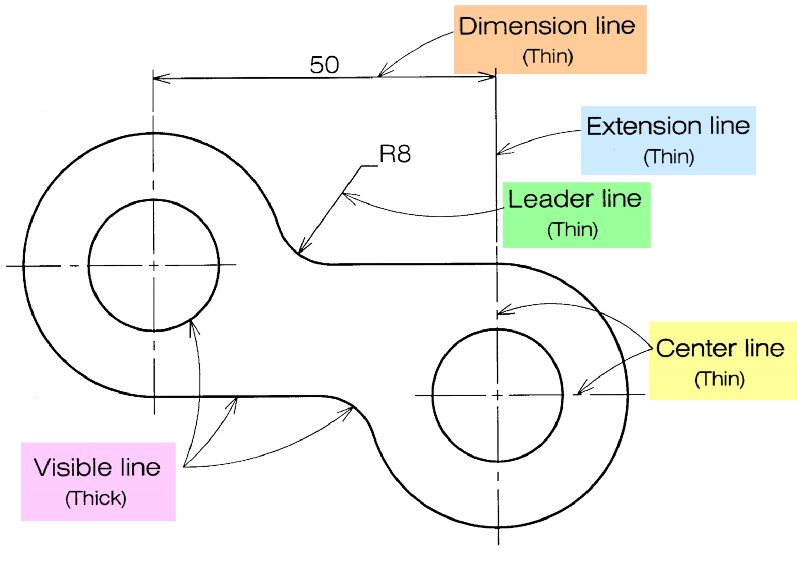
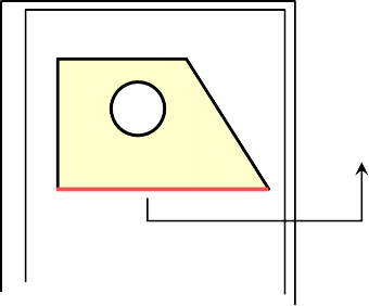
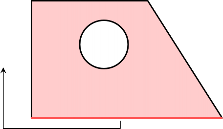
Basic Line Types

Continuous thick line Visible line

Continuous thin line Dimension line Extension line Leader line

Chain thin line Center line

NOTE : Open the Text Book for types of line in chapter No.2 (Page No.13)
Meaning of Lines
Visible lines represent features that can be seen in the current view
Hidden lines represent features that can not be seen in
the current view
Center line represents symmetry, path of motion, centers of circles
Dimension and Extension lines indicate the sizes and location of features on a drawing
Example : Line conventions in engineering drawing