
Carpenter’s drawings
The carpenter’s drawings present the construction of the structural frame from a geometrical point of view. Since they are closely related not only to the architectural but also the structural design of the building, they derive from the cooperation of the architect with the civil engineer.
The formwork’s detailing includes accurate drawings, plans views and sections and if necessary 3D drawings-figures. These drawings also include the necessary quantities of materials-labor.
EXCAVATIONS and FOUNDATION FLOOR (Drawing C.10)
The personnel responsible for the formwork’s assembling must be notified of the excavation drawing because every possible mistake during the excavations will have an effect upon the formworks’ implementation.
The building’s foundation is faintly presented in the excavation drawing so as to confirm the general dimensions of the excavation. Moreover, this helps the growth of the building’s entire concept in all the materialization bodies involved in the work.
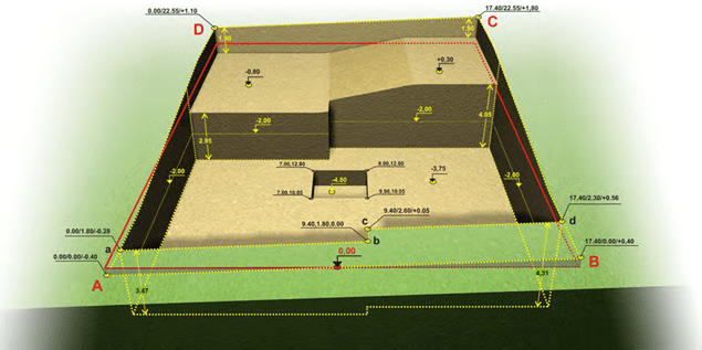
The coordinates x, y, z 2 of the chosen system are marked upon every corner of the excava- tion’s peripheral polygon. In this specific example, the origin of the coordinate system (x,y) has been defined as the lower left edge of the building land and the origin of the z axis as the middle of the forefront’s side walk which coincides with the 0.03 as set in the urban planning drawing.
The final excavation level is defined by a value upon the z axis.
In the case of a bench, only the two coordinates x and y are written upon the polygon points e.g. in the deepened excavation around at the elevator’s area.
The sections present the excavation in a simple way. The thickness4 of the leveling concrete5 is also displayed while it is very helpful to show with a faint line and the structural frame of the building that is going to be erected.
The excavation6 volumes, the filling quantities and the amount7 of the leveling concrete are writ- ten upon the drawing.
The excavation volume is separated into two quantities, the first regards the excavation below the lowest point of the ground and the other regards the excavation above the lowest point of the ground. The estimation of the first quantity is more reliable than the estimation of the second quantity.
The filling is also separated into two quantities, the first regards the quantity required for the foundation filling (upon which the basement floor will be constructed) and the second will be re- quired for the backfill of the excavation part that extends beyond the structural frame, after the construction of the basement shear walls.
In this phase of the construction, the filling quantities must be mentioned in order to be possibly combined with the collection/storage of the excavation spoil.
The amount of the leveling concrete depends upon the average necessary thickness required for the formation of a horizontal floor upon which the foundation will be sited. A higher depth accuracy and a more horizontal excavation floor surface leads to the use of a thinner concrete layer. The leveling concrete’s surface must be completely horizontal without humps because upon that surface the foundation elements will be marked and the foundation reinforcement and moulds will be positioned. Under no circumstances must that leveling take place after the con- struction of the foundation by adding excavation spoil, e.g. leveling by means of an excavator, especially in the surrounding surfaces of the foundation elements. This happens so as to avoid alterations in the soil conditions that the designer engineer has included in the structural calcu- lations.
2 During the excavation, the final floor must be defined based upon an accurate measurement in two phases: 1st) when the excavation has advanced enough, we take a measurement e.g. at -2.0 and we mark a clearly defined line around the perimeter of the pit (see the 3D figure of the excavation), 2nd) when the excavation is almost finished, we must confirm its final depth and the floor’s horizontality.
3 It is recommended to set the origin of the height measurements (0,00) as the upper level of the ground floor’s floor slab, because if we change the relative position of the building, the topographic drawing will be the only one to modify. Moreover, the technicians will easily meas- ure the floor heights from the same level without the danger of errors.
4 The thickness of the leveling concrete layer is an average value, this means that no matter how meticulous the excavation is, if the mean value of the concrete thickness is 10cm, the actual thickness in the various parts will range e.g. between 5 and 15 cm.
5 The leveling concrete is indented to level the excavation floor’s anomalies and not the anomalies of the ground’s texture, e.g. a surface that has been grooved (and disrupted) by the bucket teeth of an excavator. The leveling concrete must be casted after we firstly eliminate these marks by a mechanical or manual way.
6 As a rule, the altitudes z of the natural ground are approximate values therefore the volume of the superjacent soil is also an approximate estimation. The word Estimation of quantities includes every calculable or incalculable approximation considered in almost every work.
7 The leveling concrete must extend along the entire excavation area and not only in the erection area as it serves other reasons as well like the avoidance of a muddy surface due to rain or a faucet left open.
FORMWORK OF THE FOUNDATION and the basement floor (Drawing C.20)
Upon the surface of the leveling concrete, one must mark (a) the columns, (b) two points of every axis x0,x1, …,y0,y1,… , (c) the sides of the strip foundation and shear walls as well as the footings’ sides of the strip or the spread footings foundation. This can be done by means of a thick pencil, a special marker pen, steel pins or small wooden laths (which will be removed prior to the concrete casting), or by means of any other way.
It is recommended to temporarily define xi and yj axes either naturally (with properly fitted strings, in Greece these are called “stitches”) or electronically, so as to facilitate the determina- tion/confirmation of the remaining points and axes.
Specialized topographic personnel must determine at least the fixed points; however the lining must be confirmed with properly fitted strings and a surveyor’s tape, both by the supervisor en- gineer and by the contractors responsible for the structural frame’s erection.
When the elevator stops at the basement, its foundation must be placed around 1.40m lower than the basement level. The most effective way of construction is to normally implement the reinforcement of the elevator’s foundation together with the rest of the foundation reinforcement and before any formwork assembling, to concrete only the spread footing of the elevator. Later this will help in the proper and well-balanced positioning of the elevator’s shear wall moulds and in securing the accurate continuation of the available working space at the other floors.
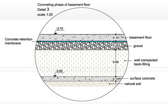
This drawing also shows the foundation filling8 which can be composed of soil, debris, debris with a final layer of gravel, or of soil and a final layer of gravel. In every case, the filling’s layers must be thoroughly compacted by means of mechanical equipment and constant water spray- ing. It is recommended to cover the final layer with a waterproof membrane (e.g. thick plastic sheet) so as to isolate waters from the substructure and to avoid absorption of the concrete’s water during the casting process.
8 Lately the foundation filling is composed of expanded polystyrene. The polystyrene pieces (of a large volume e.g. 2.0×1.0x0.5 = 1m³) might be also used for the side moulds of the foundation. However, such a case requires great attention and preliminary work in order to secure the side cover depths of the reinforcements, e.g. with the use of small steel pins, placed at pre-defined points upon the footings’ edges. If at the basement, there are drainage pipes, the channels for the piping installation can be easily opened with a saw. In is strictly forbidden to use a blow torch!
Detail of the drawing C.20
All the channels required for the piping placement of every type of installation e.g. drainage must be opened and covered prior to the final filling layer and at least before the compaction and the formation of the final surface. The installations of the foundation’s floor must be pre- sented in a separate drawing in every detail. Extra attention must be paid when defining and presenting the required vertical holes in the foundation beams for the positioning of the installa- tion pipes.
The concrete grate of the basement floor must be the same as the one used for the structural frame because it also covers the columns’ and shear walls’ layer (see §3.7.5).
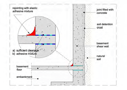
All concrete surfaces must be thoroughly cleaned and washed prior to the concreting of the basement’s floor. In the peripheral shear walls it is possible to use an adhesive emulsion, which will be placed after the meticulous cleaning and right before the concreting (see and the rele- vant detail in drawing C.30).
During an earthquake, the building’s sway up to the basement’s ceiling is considered zero and therefore, there is no obligation for a joint at the foundation and the basement. However, its po- sition must be indicated in these drawings because the reinforcement of the columns’ and shear walls’ must have the proper layout in order to be connected with the reinforcement of the corre- sponding vertical elements of the ground floor and the upper storeys.
FORMWORK of the BASEMENT’S ceiling (Drawing C.30)
The drawing of the basement ceiling’s formwork includes the formwork plan view and a charac- teristic elevation, both in 1:50 scale. Moreover, it shows the details of the two staircases in 1:20 scale and the details of the peripheral shear walls’ waterproofing in scale 1:10.
The axes and the fixed points of the columns must be re-defined in the basement level.
Two heights are mentioned upon the formwork drawing, the first regards the height of the slab’s covering and the second refers to the height of the concrete’s upper surface. Although many of these altitudes appear to be unnecessary they are written in order to avoid confusion during the formworks’ implementation.
Normally, the channels required for the positioning of the installa- tions, must be clearly indicated upon a special drawing however, if they are not extensive and complex they can be presented only upon the carpenter’s draw- ing. In case a pipe has to pass through the wall of a strip foun- dation, the designer engineer must be notified.
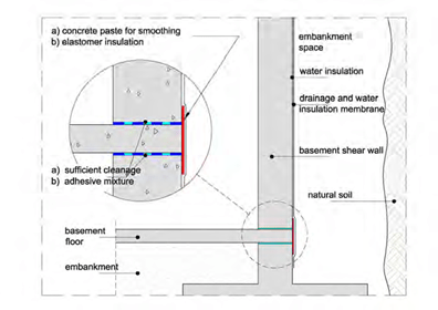
 The detail that regards the proper waterproofing of the two joints formed at the base of the peripheral shear walls where the layers of the final three concrete castings meet, is quite important. When it is possible to work at the outer surfaces, the solution is shown at the first figure while when there is no such possibility, we are limited to the internal sealing. It is noted again that the solutions mentioned in this para- graph constitute some of the numerous, analogous solutions.
FORMWORK of the GROUND FLOOR’S ceiling (Drawing C.40)
The formwork drawing of the ground floor ceiling includes the formwork and a characteristic ele- vation, both in 1:50 scale. The dashed line in the elevation is the cross section of the mezzanine that is going to be constructed in a following phase.
The drawing also includes the details of the two ground floor staircases presented in scale 1:20.
The axes and the columns’ fixed points must be re-defined in every floor so as to avoid an in- crease in the error caused by the successive point-transfers from the lower floors.
FORMWORK of the MEZZANINE’S ceiling (Drawing C.50)
The formwork of the mezzanine’s ceiling includes the formwork of the ground floor and a char- acteristic elevation, in 1:50 scale.
Moreover, it includes the details of the two staircases in 1:20 scale.
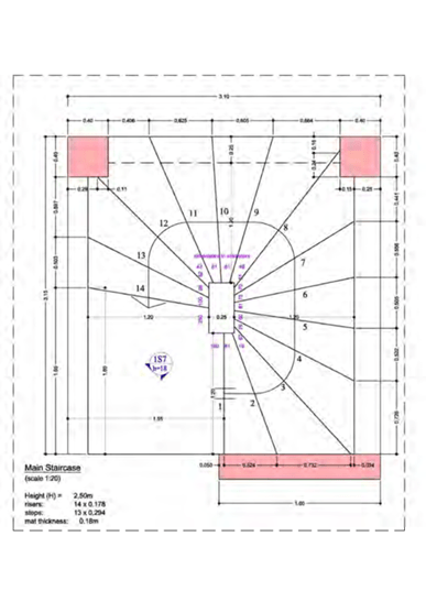
Detail of the central staircase, of the drawing C.50
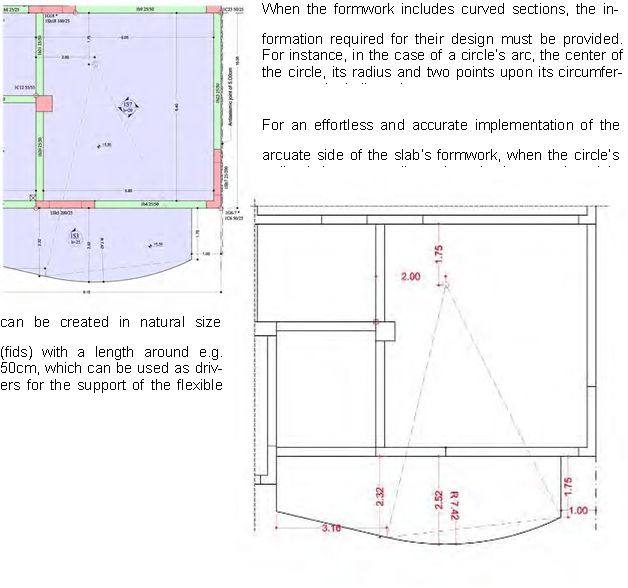
Lining of the balcony’s arc in the drawing C.50
FORMWORK of the MEZZANINE’S ceiling with thermal insulation (Drawing C.55)
The formwork’s plan view is the same with the one previously mentioned. The only difference is that the former has thermal insulation integrated inside the structural frame. This drawing is pro- vided indicatively, as a different version. However, if the structural frame is going to be con- structed with an integrated thermal insulation, then all the drawings must include the thermal insulation as well.
THE REST OF THE FLOORS (Drawings C.60,70,…) are almost alike and therefore are not in- cluded in the drawing samples.
Steel fixer’s drawings
The steel fixer’s drawings are rather complex and include a wide variety of details. The intention of this book is to present all the phases of the detailing procedure therefore, the samples of the steel fixer’s drawings include a number of details. However, these details are only a part of the details that should normally accompany the drawings.
The number of the constructional details that follow the detailing drawings of a building depends upon the size and the complexity of the work as well as upon the experience of the construction team. Many of the constructional details usually met in practice, are included in the various chapters and can be used as an example for the practically unlimited cases that one may be called to face.
The symbols of the steel fixer’s drawings have been analyzed in the previous chapters conse- quently bellow are mentioned only the titles of the drawings:
FOUNDATION FORMWORK (Drawing R.20)
FORMWORK of the BASEMENT’S ceiling (Drawing R.30) DETAILING OF THE BASEMENT’S BEAMS (Drawing R.30.B)
FORMWORK of the GROUND FLOOR’S ceiling (Drawing R.40) FORMWORK of the MEZZANINE’S ceiling (Drawing R.50)
TABLES
TABLE 1
|
Ø mm |
Mass kg/m |
Section’s area in cm² |
||||||||
|
1 pcs. |
2 pcs. |
3 pcs. |
4 pcs. |
5 pcs. |
6 pcs. |
7 pcs. |
8 pcs. |
9 pcs. |
||
|
5 |
0.154 |
0.20 |
0.39 |
0.59 |
0.78 |
0.98 |
1.18 |
1.37 |
1.57 |
1.76 |
|
6 |
0.222 |
0.28 |
0.57 |
0.85 |
1.13 |
1.42 |
1.70 |
1.98 |
2.26 |
2.55 |
|
8 |
0.395 |
0.50 |
1.01 |
1.51 |
2.01 |
2.52 |
3.02 |
3.52 |
4.02 |
4.53 |
|
10 |
0.617 |
0.79 |
1.57 |
2.36 |
3.14 |
3.93 |
4.71 |
5.50 |
6.28 |
7.07 |
|
12 |
0.888 |
1.13 |
2.26 |
3.39 |
4.52 |
5.65 |
6.78 |
7.91 |
9.04 |
10.17 |
|
14 |
1.210 |
1.54 |
3.08 |
4.62 |
6.16 |
7.70 |
9.24 |
10.78 |
12.32 |
13.86 |
|
16 |
1.580 |
2.01 |
4.02 |
6.03 |
8.04 |
10.05 |
12.06 |
14.07 |
16.08 |
18.09 |
|
18 |
2.000 |
2.54 |
5.08 |
7.62 |
10.16 |
12.70 |
15.24 |
17.78 |
20.32 |
22.86 |
|
20 |
2.470 |
3.14 |
6.28 |
9.42 |
12.56 |
15.70 |
18.84 |
21.98 |
25.12 |
28.26 |
|
25 |
3.850 |
4.91 |
9.82 |
14.73 |
19.64 |
24.55 |
29.46 |
34.37 |
39.28 |
44.19 |
|
28 |
4.833 |
6.16 |
12.32 |
18.47 |
24.63 |
30.79 |
36.95 |
43.10 |
49.26 |
55.42 |
|
32 |
6.310 |
8.04 |
16.08 |
24.12 |
32.16 |
40.40 |
48.24 |
56.28 |
64.32 |
72.36 |
Example: 4Φ14 correspond to a section of 6.16cm² and have a mass equal to 4*1.21=4.84kg Example: 2Φ20 correspond to a section of 6.28cm² and have a mass equal to 2*2.47=4.94kg
TABLE 2
Light structural wire meshes – Β500Α – ΕLOΤ 1421-2
|
Sheet dimensions |
Mesh type |
Cross wires |
Longitudinal wires |
Theoreti cal sheet mass |
||||
|
No. |
Diameter |
Distance |
No. |
Diameter |
Distance |
|||
|
(m) |
(mm) |
(mm) |
(mm) |
(mm) |
(Kg) |
|||
|
5,00 x 2,15 |
T131 |
33 |
5,0 |
150 |
15 |
5,0 |
150 |
21,5 |
|
5,00 x 2,15 |
T188 |
33 |
6,0 |
150 |
15 |
6,0 |
150 |
32,4 |
|
5,00 x 2,15 |
T196 |
50 |
5,0 |
100 |
22 |
5,0 |
100 |
33,5 |
Example: one wire mesh Τ188 has square openings 15×15 cm and rebars Φ6/15 which corresponds to 1.88 cm²/m, in both directions. Its mass is equal to 32.4kg
TABLE 3
|
Distances in cm |
Reinforcement’s section in cm² |
Pieces per m |
||||||
|
Ø 6mm |
Ø 8mm |
Ø 10mm |
Ø 12mm |
Ø 14mm |
Ø 16mm |
Ø 18mm |
||
|
6.00 |
4.71 |
8.38 |
13.09 |
18.85 |
25.66 |
33.52 |
42.41 |
16.70 |
|
6.50 |
4.35 |
7.73 |
12.08 |
17.40 |
23.68 |
30.95 |
39.15 |
15.40 |
|
7.00 |
4.04 |
7.18 |
11.22 |
16.16 |
21.99 |
28.73 |
36.36 |
14.30 |
|
7.50 |
3.77 |
6.70 |
10.47 |
15.08 |
20.52 |
26.81 |
33.93 |
13.40 |
|
8.00 |
3.53 |
6.28 |
9.82 |
14.14 |
19.24 |
25.14 |
31.81 |
12.50 |
|
8.50 |
3.33 |
5.91 |
9.24 |
13.31 |
18.11 |
23.66 |
29.94 |
11.80 |
|
9.00 |
3.14 |
5.59 |
8.73 |
12.57 |
17.10 |
22.34 |
28.28 |
11.10 |
|
9.50 |
2.98 |
5.29 |
8.27 |
11.90 |
16.20 |
21.17 |
26.79 |
10.50 |
|
10.00 |
2.83 |
5.00 |
7.85 |
11.31 |
15.39 |
20.11 |
25.45 |
10.00 |
|
10.50 |
2.69 |
4.79 |
7.48 |
10.77 |
14.66 |
19.15 |
24.24 |
9.50 |
|
11.00 |
2.57 |
4.57 |
7.14 |
10.28 |
13.99 |
18.28 |
23.14 |
9.10 |
|
11.50 |
2.46 |
4.37 |
6.83 |
9.84 |
13.39 |
17.49 |
22.13 |
8.70 |
|
12.00 |
2.36 |
4.19 |
6.54 |
9.42 |
12.83 |
16.76 |
21.21 |
8.30 |
|
12.50 |
2.26 |
4.02 |
6.28 |
9.05 |
12.32 |
16.09 |
20.36 |
8.00 |
|
13.00 |
2.17 |
3.87 |
6.04 |
8.70 |
11.84 |
15.47 |
19.58 |
7.70 |
|
13.50 |
2.09 |
3.72 |
5.82 |
8.38 |
11.40 |
14.90 |
18.85 |
7.40 |
|
14.00 |
2.02 |
3.59 |
5.61 |
8.08 |
11.00 |
14.36 |
18.18 |
7.10 |
|
14.50 |
1.95 |
3.47 |
5.42 |
7.80 |
10.62 |
13.87 |
17.55 |
6.90 |
|
15.00 |
1.89 |
3.35 |
5.24 |
7.54 |
10.26 |
13.41 |
16.97 |
6.70 |
|
15.50 |
1.82 |
3.24 |
5.07 |
7.30 |
9.93 |
12.97 |
16.42 |
6.50 |
|
16.00 |
1.77 |
3.14 |
4.91 |
7.07 |
9.62 |
12.57 |
15.90 |
6.30 |
|
16.50 |
1.71 |
3.05 |
4.76 |
6.85 |
9.33 |
12.19 |
15.42 |
6.10 |
|
17.00 |
1.66 |
2.96 |
4.62 |
6.65 |
9.05 |
11.83 |
14.97 |
5.90 |
|
17.50 |
1.62 |
2.87 |
4.49 |
6.46 |
8.79 |
11.49 |
14.54 |
5.70 |
|
18.00 |
1.57 |
2.79 |
4.36 |
6.28 |
8.55 |
11.17 |
14.14 |
5.60 |
|
18.50 |
1.53 |
2.72 |
4.25 |
6.11 |
8.32 |
10.87 |
13.76 |
5.40 |
|
19.00 |
1.49 |
2.65 |
4.13 |
5.95 |
8.10 |
10.58 |
13.39 |
5.30 |
|
19.50 |
1.45 |
2.58 |
4.03 |
5.80 |
7.89 |
10.31 |
13.05 |
5.10 |
|
20.00 |
1.41 |
2.51 |
3.93 |
5.65 |
7.69 |
10.05 |
12.72 |
5.00 |
Example: the reinforcement Φ12/15 corresponds to a section of 7.54 cm²/m. The equivalent reinforcement is Φ10/10 which corresponds to a section equal to 7.85 cm²/m


