
Slabs
The general concepts regarding slabs were explained in paragraph 1.2.3 while the concepts regarding their behavior were explained in paragraph 1.4.1. This paragraph refers to the rules concerning the slab reinforcement.
One-way slab (simply supported slab)
The following describe the way to reinforce a one-way (simply supported) slab.
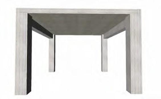
The structural frame consists of four columns, two beams and one slab
<project: slabs10 >
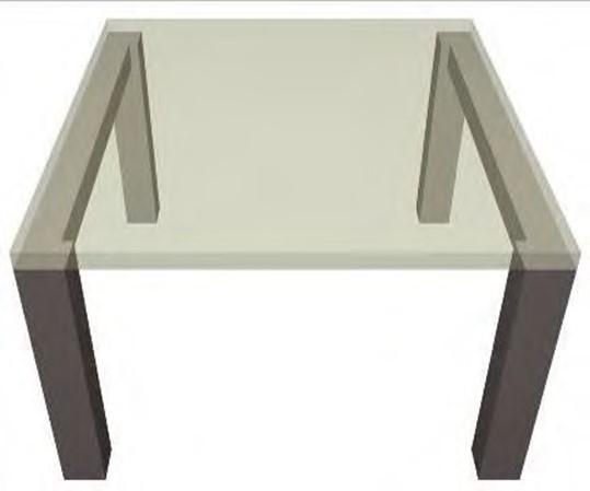
The one-way slab is supported by two beams.
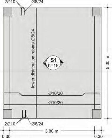
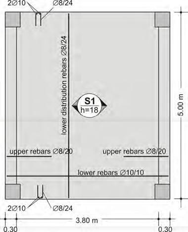
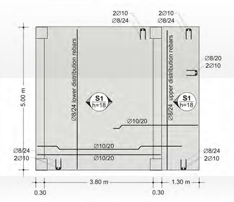
The example regards slab S1 which is 18cm thick, its primary dimension is equal to 0.30+3.80+0.30=4.40m and its secondary dimension to 5.0m. The slab sits upon beams b1 and b2 which are supported by column pairs K2, K4 and K1, K3 respectively.
Usually, when a slab sits upon a beam the support is considered to be pinned5.
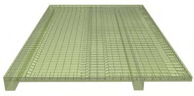
The following figure is called carpenter’s formwork drawing6. It symbolically illustrates the structural frame of reinforced concrete.
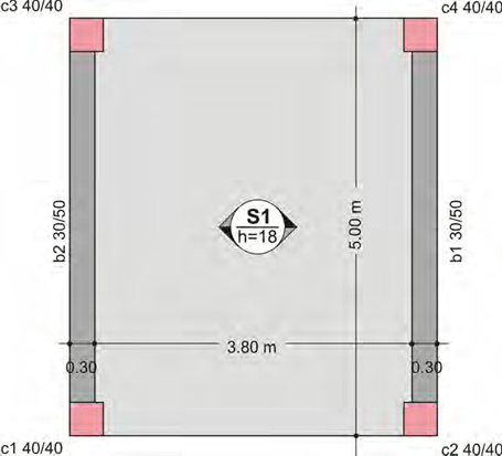
The carpenter’s formwork drawing regards the formation of the slab’s moulds

5 The simultaneous concreting of a slab and a beam results to a monolithic support between them. This causes the appearance of torsional moments to the beam and negative bending moment to the support area of the slab. The magnitude of these moments depends upon the beam’s elastic stiffness which is relatively large. However, after the formwork’s removal it is dramatically decreased due to creep i.e. the deformation caused with time. According to the regulation, the effect of the beam’s rigidity may be neglected but when it is not neglected it must be taken equal to 1/10 of the elastic stiffness. The effect of the torsional stiffness is practically zero except in cases of a static sys- tem’s equilibrium as it happens in the example of § 3.4.5 (beam under torsion).
6 Formwork is the term given to moulds into which concrete is poured. The wooden formwork is built on site out of timber. The formwork drawings are allocated for two specific uses one for the creation of the formwork by the carpenter and thus it is called carpenter’s formwork drawing and one for the steel reinforcement implementation by the steel fixer which is called steel fixer’s formwork drawing.
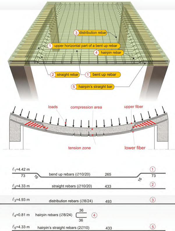
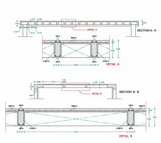
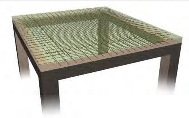
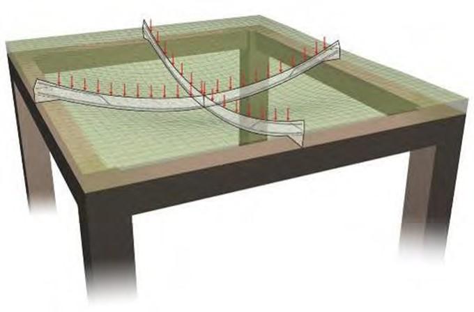
Behavior and reinforcement of one-way slab
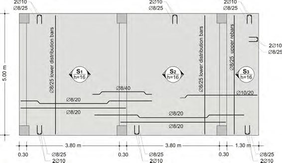
The steel fixer’s formwork drawing regards the slab’s reinforcement
The slab of the above example has four types of reinforcement:
 1st) primary reinforcement
In a one-way slab the need for reinforcement appears mainly in the span and towards the bending direction. The necessary bars are placed based on the amount of the calcu- lated required reinforcement. In this specific case the provided bars are Φ10/10. This means that Φ10 rebars have been placed every7 10cm.
 2nd) secondary reinforcement or distribution reinforcement
Apart from the primary reinforcement that is placed parallel to the deformation direction, there is also need for reinforcement in the other, the secondary direction. In that direc- tion, the placed rebars are Φ8/24 which means that bars with a Φ8 diameter have been placed every8 24cm.

7 The reinforcement in slabs is calculated per 1m of width. In this specific example, in every 1 m (100 cm) of slab width there are 100/10=10 rebars. The Φ10 rebar has a cross-section area of π*d2/4=π*1.02/4=0.785cm2 and therefore, the total amount of reinforcement placed in 1m is 10bars*0.785=7.85cm2. This value can be taken directly from table 3.
8 The Φ8 rebar has a cross-section area equal to π*0.82/4=0.50cm2. The rebars placed in 1m are 100/24=4.17 consequently, the total amount of secondary reinforcement is 4.17*0.50=2.09cm2/m. This value can also be taken directly from table 3 in ½*Φ8/12
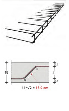
 3rd) free edge reinforcement
The free edges of slabs are more susceptible to stresses and therefore, in these areas hairpin reinforcement is placed. Its proper position is secured by means of two bars placed inside its corners.
Hairpin reinforcement is easily formed by a folded wire mesh (see and paragraph 2.6.1).
 4th) support reinforcement
The minimum required reinforcement in the support areas is provided by two ways:
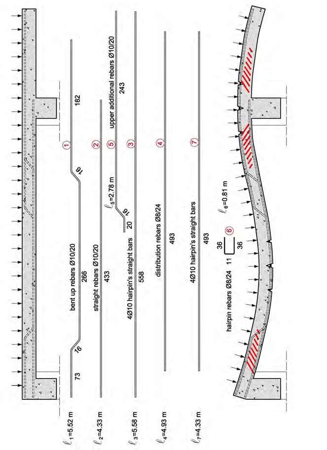
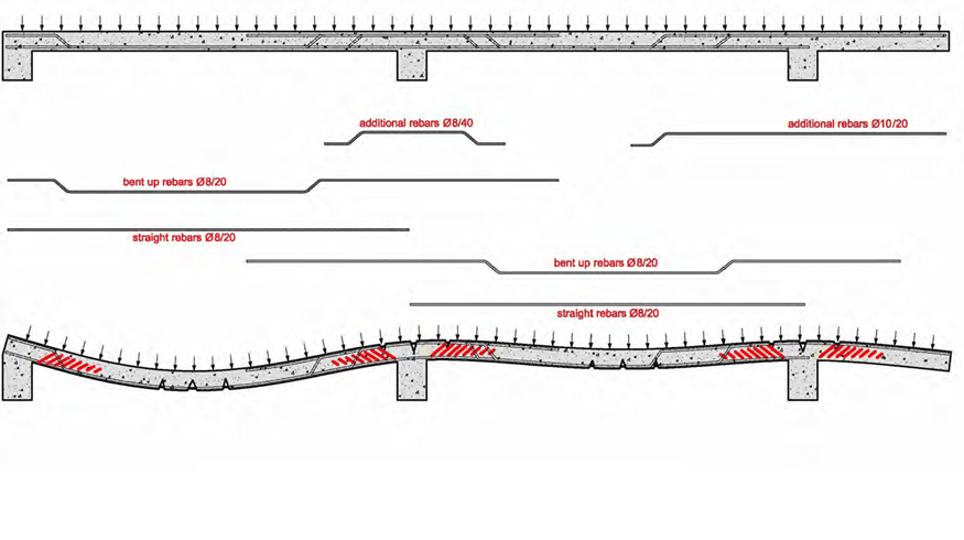
1st way: Half the span rebars i.e. Φ10/20 are shaped with bends at their ends (in every two bars one is straight and one is bend- up). The other half span rebars are formed with a straight length. That way has been followed in this specific example.
2nd way: All span rebars i.e. Φ10/10 are manu- factured and implemented with a straight length while in the upper part of the support areas additional straight rebars are placed.
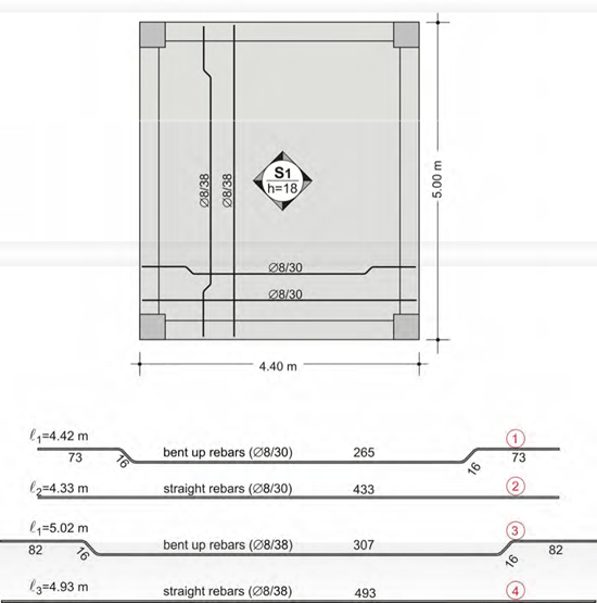
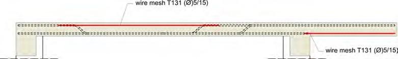
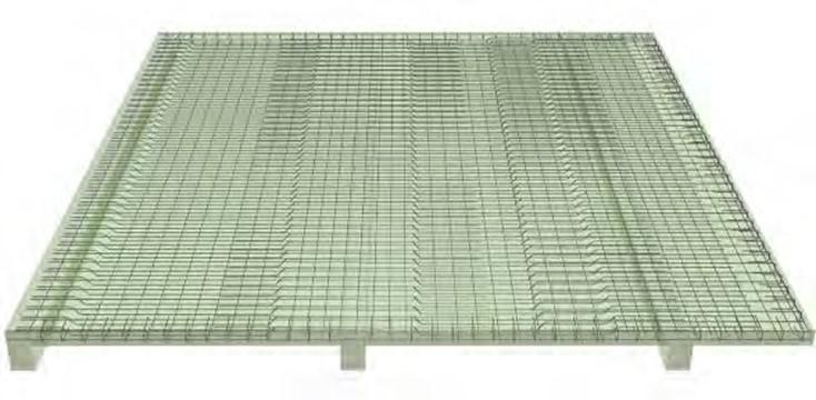
For an effortless and economical implementation, when using straight-length rebars it is obliga- tory to use industrial wire meshes as shown at the following figure.
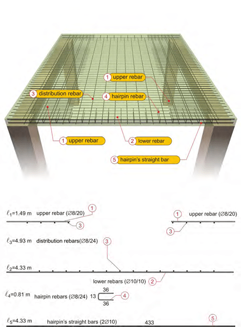
Reinforcing the one-way slab of the above example by means of straight-length bars
<project: slabs15>
In case a slab is reinforced only with straight-length bars which, as a rule, means reinforcement with wire meshes, the steel fixer’s formwork drawing is shown at the figure below.
The steel fixer’s formwork drawing of a one-way slab, reinforced with straight-length bars
Two-way slab
If two beams are added under the free edges of the slab in the previous example, then the slab S1 becomes a two-way slab.
The two-way slab S1 is supported by four beams
<project: slabs20>
The behavior of a two-way slab is similar to that of a one-way slab the only difference is that the former works in both directions.
The reinforcement rules are also similar in both directions.
Behavior of a two-way slab
The steel fixer’s formwork drawing of a two-way slab
For reasons regarding behavior, safety and economical design, the two-way slab is far more efficient than the equivalent one-way slab9.
9 The two-way slab of the example, with the same dimensions and the same applied loads as those in the one-way slab, requires reinforcement equal to Φ8/15 in the primary (most heavily loaded) direction and Φ8/19 in the secondary direction. The primary direction reinforcement Φ8/15, is equal to 3.35cm2/m (from table 3) which corresponds only to 43% of the reinforcement required in the equivalent one-way slab which is equal to 7.85 cm2/m.
One-way slab connected to a cantilever
The behavior and the reinforcement of a one-way slab connected to a cantilever are described below. If the first slab is a two-way slab both the behavior and the reinforcement rules are ana- logous.
One-way slab connected to a cantilever <project: slabs30>

Note:
The bars shown at this example constitute the primary and the secondary reinforcement re- quired by the static calculations. They are placed in parts of the lower and upper slab surfaces and they secure the structure’s strength against the primary loads defined by the regulations. However, apart from the primary loads there are other most of the times incalculable loads that cause less intense, secondary stresses. These are successfully carried in areas with reinforce- ment while in all other areas they incline the formation of cracks. These type of stresses, except from concrete’s drying shrinkage, are differential deformations caused by sudden differential stressing, e.g. the placement of building materials upon a part of a slab, mainly though they are deformations caused by earthquake forces. The cracking does not affect the structure’s strength but it arises serviceability and aesthetic issues. The cracking’s control can be achieved by an additional light coherence reinforcement 10 placed at the lower and upper slabs’ surfaces in the areas that remain unreinforced.
In the upper floor slabs and generally, during the construction stage, in all weather-exposed slabs it is almost mandatory to place a light wire mesh so as to avoid the cracking caused main- ly due to the weather conditions present throughout the building’s construction.
The coherence reinforcement is provided by a light wire mesh e.g. Τ131, placed at the lower surface of the cantilever slabs and at the upper part of the slabs’ span which does not have pri- mary reinforcement, as shown at the above figure.
The coherence reinforcement’s cover depth is secured as shown also in § 2.6.1.
10 The coherence reinforcement is analogous to the surface reinforcement which is required by all regulations only for cracking prevention, when due to adverse environmental conditions present throughout the structure’s service life, there is a large reinforcement cover depth.
Continuous slab connected to a cantilever
In the case of three continuous slabs the third of which is a cantilever, the behavior and the rein- forcement have the following form.
Two continuous one-way slabs connected to a cantilever
<project: slabs40>


Ribbed slabs
The ribbed slab (or zoellner slab) is something between a slab and sum of beams. Generally, during a seismic event ribbed slabs, like rigid ones, are not stressed along the vertical direction therefore, their reinforcement is practically independent of the earthquake forces.
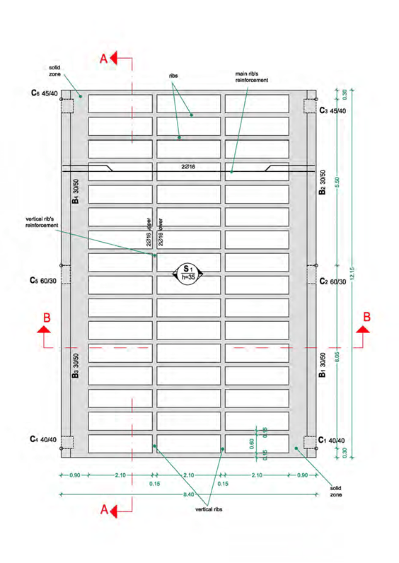
The rib reinforcement follows the same rules with the beam reinforcement. However, mainly as far as the stirrups are concerned, the amount of placed rebars is not as large as it is in beams. Between the ribs, the slab is usually reinforced with a common wire mesh11.
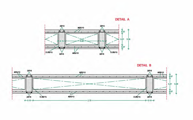
Reinforcement details of a ribbed slab
When the ribbed slab is continued by other slabs (as it commonly is), the support areas are called to withstand severe moments and shear forces, therefore the ribs’ width is preferred be greater than e.g. 20cm.

11 Since slabs are not considered to carry earthquake loads, standardized wire meshes B500A (according to table 2) can be used in order to provide both the slab reinforcement and the ribs’ stirrups. In this specific example, a Τ196 (Φ5/10) wire mesh could be used for the slab rein- forcement and a Τ188 (Φ6/15) wire mesh could be used for the formation of the ribs’ stirrups.
Sandwich slabs
In reality, sandwich slabs are ribbed slabs with a slab placed both to their upper and lower sur- face.
Sandwich slabs may have the disadvantage of a larger weight compared to the ribbed ones but on the other hand, they have the advantage that their spans and supports behave in the same proper way. Their construction is more demanding than that of the common ribbed slabs but at the same time, they have the advantage of a uniform, solid lower surface.
As shown bellow, the only difference between the prior mentioned ribbed slab left as it is and the prior mentioned ribbed slab but calculated and constructed as a sandwich slab, is the differ- ent sections.
Generally, it is advised to use sandwich slabs only in cases of large slab thickness.
Reinforcement details of a sandwich slab
RULES FOR THE DETAILING OF SLAB REBARS
This paragraph refers to some of the rules that one should follow when bending up slab rebars. These rules apply to both one-way and two-way slabs, with usual lengths and commonly ap- plied loads and only when the reinforcement detailing is not provided by another more accurate way.


-
In one-way slabs, the length l is equal to the distance between the two edges upon which the slabs are supported.
- In two-way slabs, the length l is regarded equal to the smaller dimension of the slab.
-
In cantilever slabs, the length l equals the distance between the support and the opposite free edge of the slab.
- When a slab’s support is considered fixed, the previous corresponding rules apply.
-
When the lower rebars are being bent in order to provide support reinforcement, the straight created upper horizontal part must be extended by the anchorage length.
-
The anchorage length of the rebar (dashed line) is directly proportional to the diameter Φ and the concrete grade and reversely proportional to the steel class (in the Greek code the standard steel class is B500). In usual cases the anchorage length is in the order of 50cm. The use of industrial wire mesh is favorable for the anchorage length.
-
Bending the rebar at 90° or 135° in the edges of pin supports is positive for the proper be- havior of slabs. However, as a rule, it is not necessary especially in high concrete grades.
-
If the formwork drawings contain specific dimensions of the reinforcement bars detailing then these predominate over the above mentioned empirical rules.


