
Beams
General
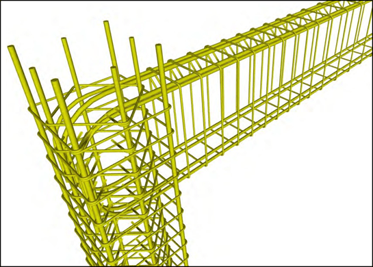
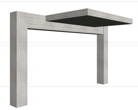
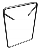
The following figure shows one beam supported by two columns.
This beam, due to its elasticity (stiffness) and the loads that it bears (self weight, supported slab, walls, etc), is deformed by the way mentioned in chapter 1.4.2 The reinforcement placed inside beams is comprised of the longitudinal bars and the transverse reinforcement in the form of stirrups (ties).
The longitudinal rebars are placed in order to resist the flexural tensile stresses that appear along the beam axis while stirrups are used to carry the diagonal tensile stresses caused by shear.
Moreover, stirrups help in the critical areas’ confinement.
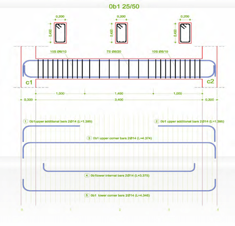
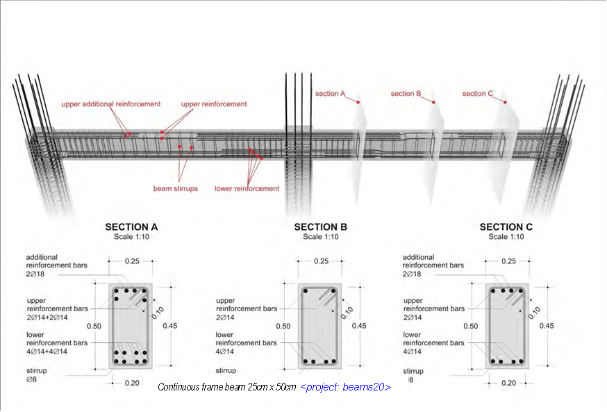
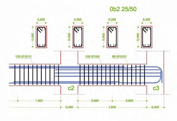
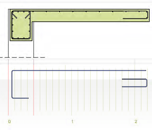
Details of longitudinal rebars in characteristic areas of the beam.
The number placed in front of the beam b1 indicates the floor that this beam belongs to. In this case, it is the number 0 which corresponds to the ground floor4. 1 represents the 1st floor, 2 the 2nd floor, -1 the first basement and so on. This means that the beams’ number prefix is …,-2,- 1,0,1,2,…

4 in places where the first floor above ground is not referred to as ground floor but as 1st floor, number 1 represents the ground floor and the beams’ number prefix is …,-2,-1,1,2,3,…


Since most of the times beams with names b1, b2 etc appear in all floors, it is compulsory to use the prefix both in the constructional drawings and in the beams’ labels so as to avoid confu- sion with the drawings and the various materials used (these are specified in the beam’s labels).
The label 10SΦ10/10.0 means that 10 stirrups, with a Φ10 diameter and 10cm spacing, will be provided at the critical length of the beam, which in this case is equal to 1m. In the detail draw- ing of the following continuous slab, the label 12SΦ8/17 that refers to the beam’s span, which has a length equal to 2m, indicates that 12 stirrups with a Φ8 diameter will be placed around every 17cm (the exact distance between them is 200/12=16.7cm).
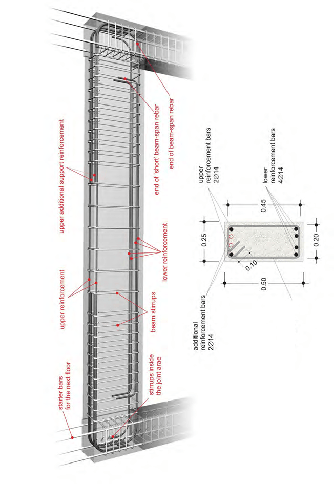
A seismic ground motion causes reverse bending moments to the beam.

In the joint area of an earthquake resistant frame both the upper and the lower reinforcement are fully anchored.
The stirrups hold the rebars in place and they carry the diagonal tensile forces that usually shift direction.
The beam’s area next to the face of the column is characterized as ‘critical’ because it carries the largest stresses. Its length is equal to twice the depth of the beam (in our example 2*0,50=1,00 m). The stirrups placed at the critical areas must be narrow spaced and properly closed.
The beams’ width must be greater or equal to 20cm and at least 2Φ14 must go through the full length of the beam both at the top as well as at the bottom.
Continuous beam
The continuous beam is a commonly accepted term for a succession of two or more colinear beams which are supported by columns or by other beams with no antiseismic behavior re- quirements. It is not frequently constructed in earthquake prone countries like Greece. On the other hand, it is used in a large scale in areas with low seismic activity.
As far as the reinforcement is concerned, the construction of a continuous beam with no seismic behavior requirements is much more simple compared to the earthquake resistant beams.
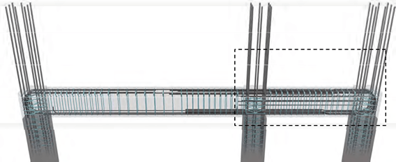
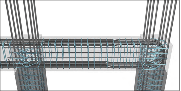
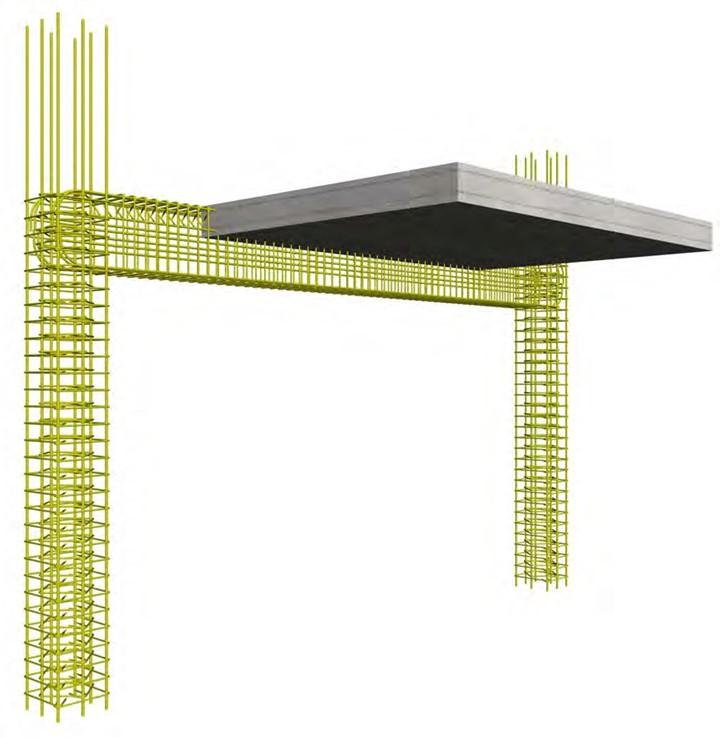
The following figure shows, in a photorealistic view, two continuous frame beams with antiseis- mic requirements.
The detail sections show the proper placement of the beams’ reinforcement.


Reinforcement placement
Placing rebars along the length of the beams (longitudinal reinforcement):
In two successive beams that have the same section, the longitudinal rebar pairs placed both inside the upper and lower stirrup corners are colinear therefore, it is compulsory for the one to be bent so as to bypass the other. This bending must be vertically done in order to have ade- quate space for the proper concreting.
When using large diameter rebars (greater than Φ14), the bending cannot be manually done during the im- plementation therefore, it has to be done prior to placement by means of a double bending machine.
An effective rule to follow in cases like this is: (a) the bars placed in beams with odd numbers 1,3,5,… to be straight and (b) the corner bars placed in beams with even numbers 2,4,6,… to be appropriately bent.
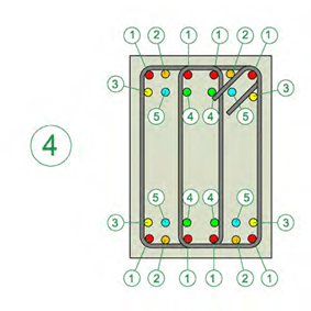
Placing rebars in a beam’s cross section
The case (1) shows, in priority order, the possible rebar positions in a rectangular 25/50 beam (with no slab on top).
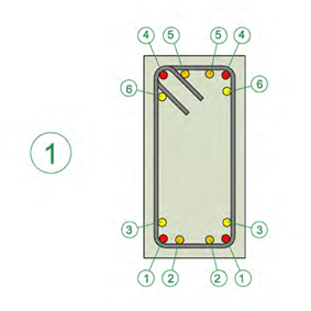 At the lower part of the beam, the first rebars to place are the corner bars 1, then the internal bars 2 followed by one bar 3 or if it is necessary by a second bar 3.
At the upper part of the beam the same things ap- ply as well.
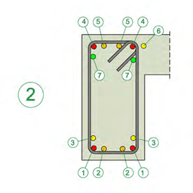 The case (2) shows a “Γ” section beam where at the upper part, the priority 6 is given to the rebar placed outside the perimeter of the stirrup. The bar 6 must be positioned at a distance around 2cm away from the stirrup so as to avoid damage during additional operations by plumbers, electri- cians etc. This bar should be fitted upon the slab support rebars or upon the upper leg of the stirrup which might close outside the beam’s body.
Notes:
-
Rebars in place 6 may be used only when they cross the adjacent column or when they are anchored inside it.
-
In many cases, the stirrup cage is constructed and fitted inside the beam half closed so as to facilitate the implemen- tation of the longitudinal rebars. Moreover its upper leg has a larger length which allows, after the placement and the wiring of the longitudinal rebars, its trouble free closing with the use of the proper machinery.
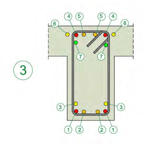
The case (3) shows a “T” section beam, where at the upper part the priority 6 is given to the rebars outside the perimeter of the stirrup.
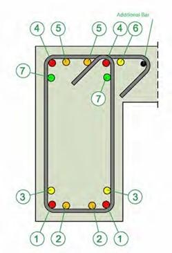
The case (4) shows in priority order, the possible rebar positions in a rectangular 35/50 beam with a four legged stirrup. It is mandatory to place firstly the corner bars 1, then one rebar 2 and the sec- ond rebar 2 followed by the rebars 3. If the rein- forcement requirements are so large that cannot be met by an increase in the rebar diameter, bars 4 and 5 of the second layer are placed one by one.
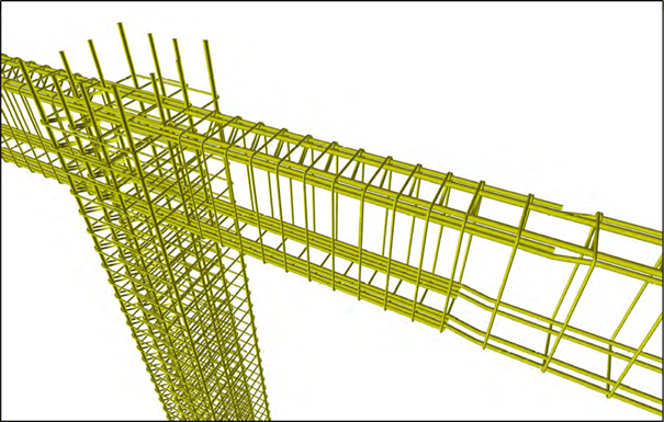
Short beam
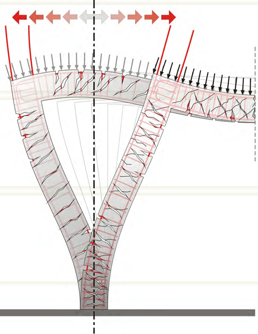
A beam which has a short span length compared to the span length of the other beams that be- long to the same floor, might not have a serious bending problem but as a rule, its behavior is greatly affected by intense shear stresses. A part of the applied shear forces comes from the gravity loads however, the largest part is caused by the earthquake ground motion. Apart from the intensity
of the shear forces, the short beams must counteract the effects of these forces direction shifting in the duration of the seismic event. This means that we have cyclic shear loading that tends to disintegrate the element. In short beams, the diagonal tensile stresses are carried by placing a strong transverse reinforcement towards all directions i.e. by placing narrow spaced, properly closed stirrups and lateral rebars. Theoretically, the best solution is to use special “X” shaped stirrups, however most of the times, this is a technically challenging proce- dure.
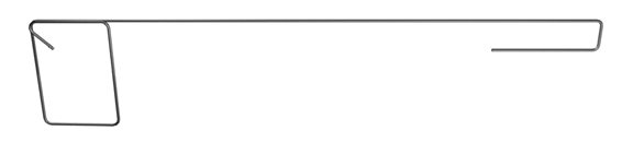
The right beam might be short compared to the left one but it has a larger amount of reinforcement (both longitudinal and vertical). <project: beams30>
The short beam is reinforced with (a) narrow spaced strong stirrups and (b) with lateral rebars.
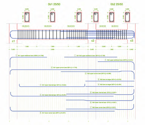
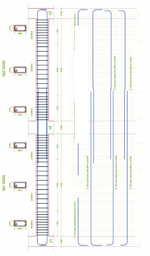
Continuous beam’s reinforcement details
Detail drawing of the short beam rebars
Beam under torsion
When a beam supports a slab (or when it carries another beam only on its one side), it is sub- jected to direct torsion.
Beam under direct torsion <project: beams40>
For common buildings in areas with high seismic activity, torsion is a quite dangerous stress condition, because:
-
It is a statically determined stress. This means that if a failure occurs there is no possibility for transition to another static state.
-
The rotations caused to the beam due to creep are relatively large thus leading to large slab deformations.
-
Failure is caused by shear stresses therefore, it is of a brittle nature and consequently there are no signs for the impending failure.
-
It is not easy for the technicians to understand that the formwork of the elements under tor- sion must not be removed in the usual time. On the contrary, the formwork must remain in place until the following-phase-casted-concrete that affects these elements is adequately hardened.
-
Reinforcing beams subjected to torsion follows special rules. In order to apply these rules, one does not only require thorough knowledge but also extreme care during the implemen- tation.
 Either the beam section is hollow or solid it counteracts with the torsional moment and maintains a state of equilibrium with a closed flow of torsional shear stresses, in a peripheral zone.
Due to the high shear strength requirements, beams under tor- sion, are usually constructed with a large width. That way the beam’s section approximates the square shape.
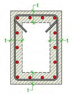
Torsion causes diagonal tensile stresses along the entire pe- rimeter of the beam and in order these stresses to be carried both longitudinal and vertical reinforcement is required. The longitudinal reinforcement at the upper and lower side of the beam is provided by the upper and lower rebars, while the lon- gitudinal reinforcement of the side-faces is provided by the re- bars placed along the stirrups’ legs depth.
 The longitudinal rebars of the support areas are called to withstand the highest torsional stresses. Therefore, in order to behave in the required way, all rebars placed at the upper, lower and side parts of the beam must be properly anchored inside the column.
In order for the vertical reinforcement i.e. the stirrups to carry the re- quired stresses; they must be properly closed therefore, it is mandatory to be formed with a double hook.
In order to be able to place the slab reinforcement, the beam’s formwork must have its back side-face open.
The rebars of the slab supported by a beam, must be anchored at least with a double bend, as shown at the above detail. The rest of the reinforcement has to abide by the rules regarding cantilevers as explained in the following chapter.
In order to be able to place the slab’s rebars, the formwork must have its back side-face open. Alternatively, the vertical slab bar could be constructed 5cm shorter so as to be placed unob- structed above the longitudinal reinforcement at the bottom part of the beam.
There is also another more complex but old and well-tried practice: in the slab area where tor- sion appears, the stirrup and the slab rebar are formed with one single bar, as shown at the fig- ure bellow.
The reinforcement solution with unified stirrups – rebars in the slab area
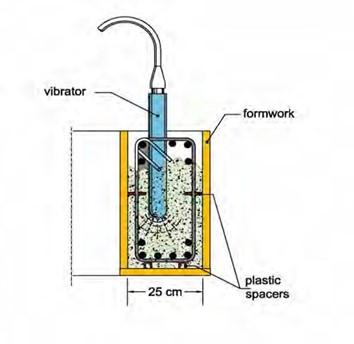
The feasibility of concrete casting in beams
In the construction of a building, the proper reinforcement implementation will be proved only during the concreting process. The steel fixer must always bear in mind that the concrete and vibrator have to pass unobstructed between rebars. In case the columns, the beams and the slabs of one storey are simultaneously casted, the reinforcement implementation requires even more attention and care.
Since the proper concreting correlates with the proper construction, it is recommended to com- plete the concrete casting of a floor in two phases. The first phase should include the mould and the concreting of the columns and the second phase should include the mould and the concret- ing of the beams and the slabs.
The key to a feasible concrete casting is the use of a second rebar layer, as described in para- graph 3.4.2. Placing the bars at the two edges of that second layer is not a strenuous procedure since they are wired together with the stirrup legs. That way, enough space is provided for the concrete and even for the vibrator to pass vertically between the rebars.
As a rule, in earthquake resistant structures there is a large amount of reinforcement and if its implementation is not done with the proper way, most of the times, the following serious con- structional faults appear in the joint areas:
-
 In case the columns, the beams and the slabs of one storey are simultaneously casted, small or large voids appear inside the columns’ concrete mass which are extremely difficult to fill.
 -
In case the columns are casted separately from the other elements, the concrete does not pass under the rebars so as to bond with the already casted column. The worst part is that this fault cannot be seen by the eye as the concrete passes normally through the cover depth. Unfortunately, it is only until af- ter the formwork’s removal that one may re- alize if this is properly constructed.
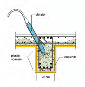
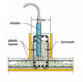
The following figures present 5 rules for the proper reinforcement implementation and the proper concrete casting:
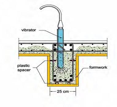
The vertical vibration is the most desirable one. (1)
In the presence of a slab, an alternative vibration possibility is the lateral placement of the device. (2)
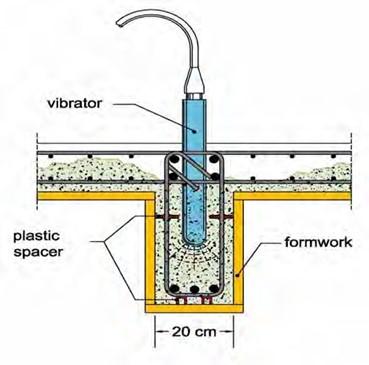
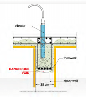
The 20cm wide beam should be avoided. However, when it is constructed it requires great care. (3)
The only way to vibrate an inverted beam is by vertically positioning the device. (4)
In the case where the beam is not connected on either side with a slab (foundation beams), the only way to vibrate the concrete is by the vertical placement of the device. (5)


