
STRUCTURAL FRAME LOADING
The structural frame is designed to withstand, in a constant basis, the vertical gravitational loads (self weight, masonry walls, floor coverings, cars, furniture, people etc) and not in a continuous but in a periodical basis, the wind and snow actions. Moreover it must always bear the “self in- duced” loadings caused by temperature changes etc.
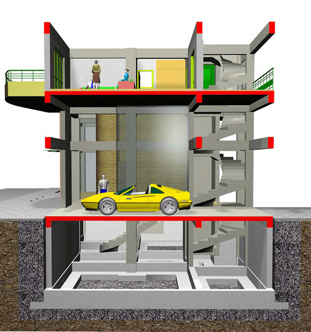
In every building like the one shown in the above figure, permanent (dead) and imposed (live) loads are applied. The latter are much lower than the former, for example 3 persons and the living-room furniture weight as much as a sin- gle m2 of slab surface while a car weights as much as a sole beam.
.
Apart from the usual loads, in earthquake prone regions, the structural frame must have enough strength surplus distributed in such a way so that in the critical moment of an earthquake, to be able to respond successfully, retaining the structure intact.
Mass is the characteristic feature of a body. The force field surrounding each body defines the types of forces applied to it. The Earth’s gravitational field applies the gravity force, otherwise referred as weight. During an earthquake, the appearance of additional horizontal accelerations causes the formation of horizontal seismic forces. These forces are applied to the structure and they constitute the structural frame loading. Structure loads can be classified into three catego- ries gravity loads, seismic loads and wind loads.
Gravity Loads
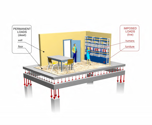
The loads applied to a structure are divided into permanent (dead loads) and imposed (live loads). The former include the self weight of reinforced-concrete structural members, of walls and coatings-coverings. The latter include loading caused by people, furniture, vehicles etc.
Dead loads
The density and the related unit weight of the materials used in construction are:
Reinforced concrete ρ=2.50 t/m3 (ε=25.0 kN/m3) Light- weight concrete for ground leveling ρ=0.80 t/m3 (ε=8.0 kN/m3) Sand mortar ρ=2.00 t/m3 (ε=20.0 kN/m3)
Marble ρ=2.70 t/m3 (ε=27.0 kN/m3)
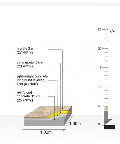
The dead mass of one m2 of the above slab is,
g = 0.15*2.50 + 0.04*0.8 + 0.02*2.0 + 0.02*2.7 = 0.5 t,
i.e. the self mass of one square meter of a usual slab is
0.5 t (weight 5.0 kN)
Water ρ = 1.00 t/ m3 (ε = 10.0 kN/m3)
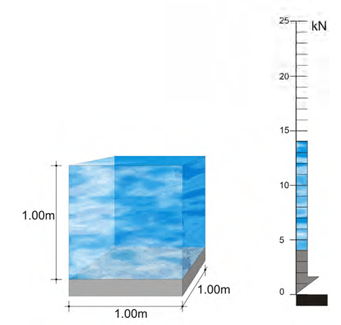
The dead mass of one m2 of a pool slab, when the pool is filled with just 1.0m of water is,
1.4 t (weight 14.0 kN)
Garden soil ρ = 2.50 t/m3 (ε = 25.0 kN/m3)
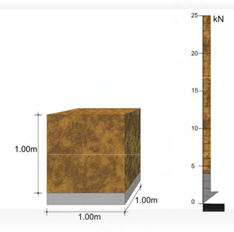
The dead mass of one m2 of a slab, with 1.0m of soil on top is
2.5 t (weight 25.0 kN)
Masonry stretcher bond ρ = 0.21 t/m² (ε = 2.1 kN/m²) Masonry Flemish bond ρ = 0.36 t/m² (ε = 3.6 kN/m²)
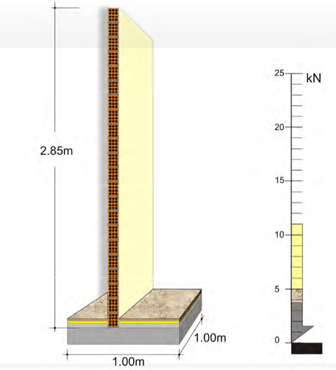
A wall of 1.0 m length, 2.85m height and 10cm thickness has a mass equal to 0.60t. (weight 6.0 kN)
Live loads
Human loading:
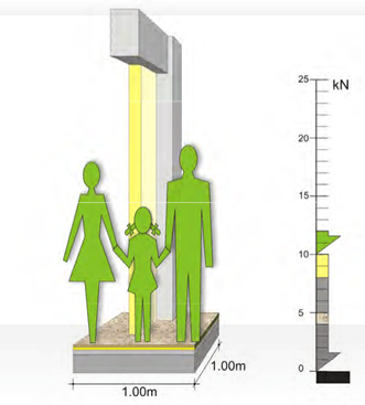
– Normal human loading ρ = 0.20 t/m² (ε = 2.0 kN/m²)
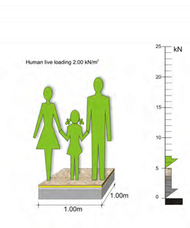
The live mass of one m2 residential building is 0.2 t (weight 2.0 kN)
– Human concentration ρ = 0.50 t/m² (ε = 5.0 kN/m²)
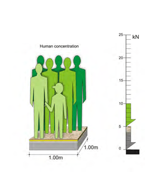
The live mass of one m² commercial area is 0.5 t (weight 5.0 kN)
Vehicle loading ρ = 0.25 t/m² (ε = 2.5 kN/m²)
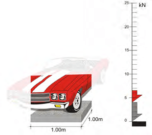
The live distributed load of 1 m² of a parking space is 0.25 t (weight 2.5 kN)
As a rule, snow loading is lower than the live load generated by the use of people and its value ranges between 0.60 and 1.50 kN/m².
Note :
In order to calculate the amount of the total loading applied to a residential structure we assume 1m² of slab i.e. 1mx1m surface.
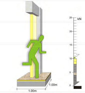
In every 1m² of floor surface, the permanent (dead) and the induced (live) masses, are in the order of 0.50t (weight 5.0KN) and 0.20t (weight 2.0KN) respectively. However when we consider the loads applied by beams, columns, walls and plasters, the total amount of the dead loads i.e.
the structure’s self weights, is greater than 10 kN/m², as opposed to the live loads that remain equal to 2kN/m². Moreover in a specific time in the structure’s life span, the possible extensive permanent loads may be around 100% in contrast to the possible extensive induced loads that may be around 30%. From all the above we realize how greater are the dead loads in compari- son to the live ones and this is one of the most important problems of structures, they “use” to many dead loads in order to bear a few live loads.
In a residential building, the maximum live loads are about 20% of the dead loads.
.
In random cases like earthquakes, the extensive live loads may reach 6% of the dead loads.
Seismic loads
The effect that a seismic action will have in a structure is determined by regarding an earth- quake with horizontal design ground seismic acceleration equal to A=α*g. Greece is divided into three Seismic Zones I, II, III and for each of these Seismic Zones the factor α takes the following values 0.16 for Zone I, 0.24 for Zone II και 0.36 for Zone III.
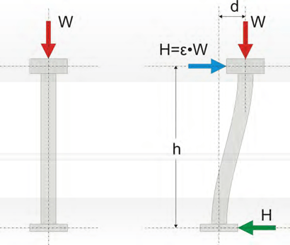
In the duration of an earthquake, a horizontal seismic force H is applied in every mass M that has gravity load W. The H force is equal to a percentage ε of the W force. ε value usually varies between 0.00 and 0.50 while in a very intense seismic action it may rise above 1.00.
The value of ε depends mainly upon the value of factor α, used for the calculation of the maxi- mum horizontal ground seismic acceleration and upon other factors like soil classification, struc- tural system’s geometry, mass center.
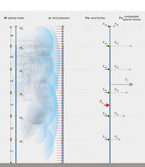
In general terms, the distribution of seismic accelerations has the form of a triangle.
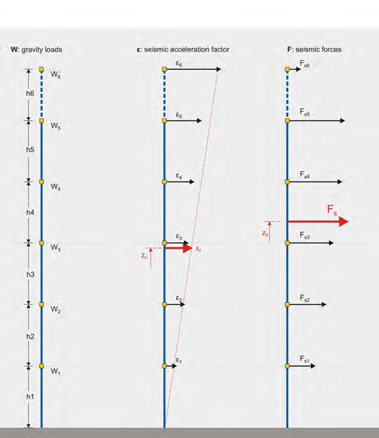
The distribution of seismic acceleration has a form similar to a triangle
The structure shown above belongs to the Seismic Zone I (seismic ground acceleration equal to 0.16), the mean value of the design seismic acceleration is around 0.12g (ε0=0.12) and the re- sultant seismic force Fs is around 1400KN. The theoretical height that this force is applied, is around the 2/3 of the structure’s total height.
Wind loading
Comparison of wind forces Fw and seismic forces Fs
In the same structure, when placed in a geographical region with intense winds, the mean value of the wind pressure is around 1.50 kN/m² and the resultant force around 400 kN. The total ser- vice load applied is 12.000 kN. Therefore the wind force is equal to 0.03% of the vertical loads and its theoretical application area is in the middle of the structure’s height. Comparing the wind and the seismic forces applied to that structure we realize that the wind effect upon the structure is at least four times smaller than the seismic effect.
Reinforced concrete structures have large self weight both during the design and the service life, consequently wind loading does not affect their behavior to the same degree as it affects timber or steel structures.
In the dimensioning of earthquake resistant structures we consider either seismic or wind forces and not simultaneous loading. As a rule, the seismic action that applies a load analogous to the wind pressures has a greater value than the wind loading, consequently, in seismic design structures are not dimensioned for wind pressures. In Greece the effect of wind is significantly smaller compared to the effect of earthquake motions even in the Zone with the lowest seismic activity.


