SECTIONAL VIEWS
INTRODUCTION TO SECTIONS
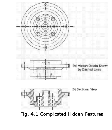
There are two methods by which we can describe the inner shape of an object. First method is to use dashed lines, as explained in Chapter No.3, but it is only valid for objects having lesser and simple hidden features. Second method is to draw sectional views which will be discussed in detail here. Dashed lines in regular orthographic views for an object with complicated interior are often much difficult to draw and further the views become confusing by the presence of a number of dashed lines, not describing the inner shape even for an experienced person. For example, in Fig. 4.1, no extra information is provided by the dashed lines of the front view rather the exterior shape is also disturbed. The visible object lines of a part are always easier to be read than the hidden lines.
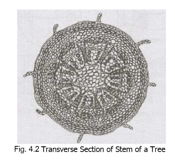
In case of a section, some outer portion of the object, which is obstructing the lines of sight to see the inner details, is considered to be removed. An orthographic view is then drawn for the remaining portion. Section may be defined as an imaginary cut made through an object to expose the interior shape. A view in which all or a portion of the view is sectioned is known as a sectional view. Consider the example of a building. A person is standing outside the building having all the doors and windows closed. He will be able to see the outer shape of that building but he cannot have an idea of what is present inside. Internal arrangement of rooms, furniture, doors, windows and almirahs will not be clear in a simple exterior view. If now the person opens the door, some of the interior details will become visible to him. The view formed after opening the door will be somewhat like a sectional view because the observer has removed the material of the door from his line of sight to see the interior. Another common example is from biology where inner parts of various organisms are required to be shown. To see the inner details of a stem or a leaf, etc., a cut is made longitudinally or transversely
removing one part while the remaining part is orthographically drawn to obtain a
longitudinal or a transverse section. The view may either be obtained by naked- eye and drawn on full scale or it may be taken using a microscope and drawn on an enlarged scale. Similarly if any fruit is cut into two parts, inner shape like arrangement of seeds may easily be seen.
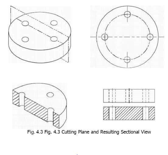
In Fig. 4.3, the process of cutting an object to obtain a section is shown. The
imaginary medium used to show the path of cutting an object to make a section is
known a cutting plane. The hidden surface limits of the drills after cutting become
visible intersections and hence the dashed lines for simple orthographic view change to
full lines i the sectional view. Further the solid portions at the level of cutting are also
shaded to separate them from the empty spaces or voids. The sectional view thus
obtained depend upon the position of cutting and a number of different sectional
views are possible for an object from the sari side, see Fig. 4.4. Hence, the position of
the cutting plan must always be specified for a sectional view otherwise it becomes
meaningless. The cutting plane is shown on that orthographic view where it appears as an edge by its symbol as given in Chapter No.2. The cutting plane may be more completely identified with reference letters and indication
of direction in which the view is taken. building drawing, only the beginning, ending of
direction is marked for a cutting plane lines in the view. Like center-line, cutting
imaginary and its symbol is usually extended.
Generally, in and the change to avoid more plane is purely from the view.
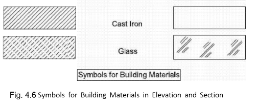
Solid metallic portions (made of Cast Iron) in sectional view are shown by section-
lining, sometimes called cross-hatching. Very fine lines are drawn at 45° with the
principal lines in the view at a uniform spacing varying from 1/16-in to 1/8-in. For
bigger portions to be cross- hatched, spacing close to 1/8-in is used, whereas, for
smaller portions, spacing close to 1/16-in is preferable. It is important to note that
there are two types of solid materials which are shown in a section. The solid
portions in the path of cutting are section-lined whereas the solids visible from
behind the cutting plane are shown by their simple orthographic views.

Spacing between the lines may easily be controlled by marking a line at the required
distance over the 45-triangle parallel to the 45° working edge. This line may be
temporarily drawn with HB-pencil or it may be drawn permanently using needle of the
divider.
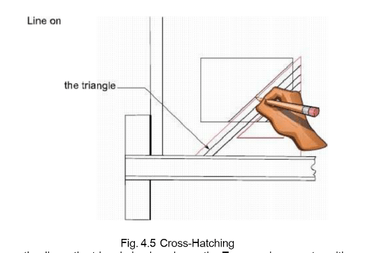
To draw section lines, the triangle is placed over the T-square in correct position and is
slided until the first corner of the portion to be sectioned coincides with the
marked line on the triangle. line is now drawn by using the working edge, this drawn line
is then coincided with the line on the triangle to give position of the triangle for the next
line. The process is repeated until all the part is section-lined. In building drawing,
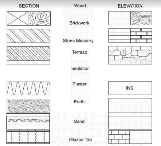
there are a number of different symbols to represent various materials like brickwork,
plain cement concrete (concrete without steel), reinforced cement concrete (concrete
with steel), earth filling, sand filling, and various steel shapes, etc. Using these symbols in
the sectional views, we can have an idea of the materials of construction even if these
are not mentioned in writing.
Main advantages of sectional views are as follows:
1. Inner shape is clearly shown without any ambiguity.
2. For more hidden features at different positions inside the object, a number of
cutting planes may be assumed and corresponding sectional views may be drawn
separately.
3. The solid portions and the voids at the level of cutting may be distinguished. 4.
Materials of construction are also communicated without writing in words.
5. Sections are often drawn to larger scales than that of the other views in order to
show the minute dimensions more clearly.

