
APPLIED GEOMETRY
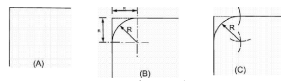
To Join Two Lines at Right Angle by a Quarter Circle
There may be two methods to locate centre of the curve so that it intersects the lines
tangentially. First method is shown in Fig. 2.14 (8) in which two center-lines are drawn
parallel to the lines to be joined at a distance equal to the radius of the circular curve.
Point of intersection of the center-lines will be the centre from where the quarter circle may be drawn. In the other method, shown in Fig. 2.14 (C), intercepts are taken on both of the lines to be Joined with the help of a compass considering center at the point of
intersection of the given lines (point 0) and radius equal to the radius of the required circle. With the same opening of the compass, two center-lines are drawn from points ‘A and ‘D, the point of intersection of these center-lines defines the centre from which the required circle may be drawn.
Fig. 2.14 Center for Quarter Circle.
2.9.2 To Join Two Parallel Lines by a Half Circle
To join two parallel lines ‘x’ distance apart by a half circle, the diameter of the circle should be x’ making the radius equal to ‘x/2. Draw one center-line exactly in the middle of the two lines and another at a distance ‘x/2 from that point where the circle must end. Point of intersection of the two center-lines will be the centre from which the half circle may be drawn with a radius equal to ‘x/2’.
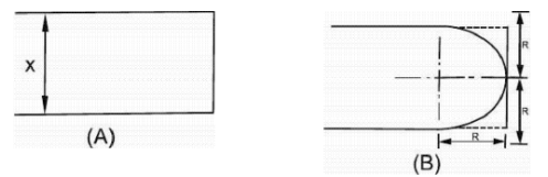
Fig. 2.15 Center for Half Circle.
To Join Two Lines at Any Angle by a Smooth Curve
Draw center-lines parallel to both the lines at a distance equal to the given radius of the
curve ‘Re, the point of intersection will be the centre from which the curve may be drawn from one line to the other.
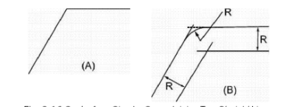
Fig. 2.16 Center for a Circular Curve Joining Two Straight Lines.
To Join Two Circles by a Smooth Curve
Suppose the two circles to be Joined are of radii R1 and R2 with their centers already located on the sheet denoted by the points A and B. These two circles are to be
joined tangentially by a third circle or curve of radius R3 whose center, C, is to be properly located. If two circles intersect tangentially, then, the point of intersection, and the two centers should be in a single straight line meaning
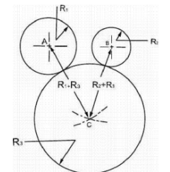
Fig. 2.17 Center for a Circular Curve Joining Two Circles.
that distance AC and BC should be equal to (R1 + R2) and (R2 + R3) respectively. To make these distances equal to the required values, draw one center-line from point A with a radius equal to (R1 + R3) and another center-line from point B with a radius equal to (R2 + R3). The point of intersection will be the required centre, C, from which the curve may be drawn in the required portion.
To Draw Line Parallel to a Given Line
There are two methods to draw lines parallel to any line at a given distance, first is shown in
Fig. 2.18 (A) while the second is shown in Fig. 2.18 (8) to (D). In the first method, compass is opened equal to the required distance between the two lines and construction curves are drawn from any two points on the given line. Common
tangent of these curves is then drawn to get the required line. In the second method, one construction curve is drawn from any point on the given line with a radius equal to
the required spacing between the two lines. Triangle-1 is then oriented in such a way that one of its edges becomes parallel to the given line while triangle-2 is placed on the other side of the triangle-1 such that the later can slide over it. Triangle-1 is then moved until its edge becomes tangent to the already drawn construction curve and the required line is drawn with it.
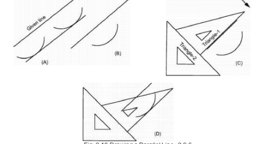
Fig. 2.18 Drawing a Parallel Line. 2.9.6
To Divide Given Length of Line into 'n’ Equal Parts
Using Divider: It is a hit and trial method in which some tries are made
starting from certain approximation, adjusting the difference after each try and
ending when the line is exactly divided into the required number of parts. To divide a
given line AB into any number of equal parts, first open the divider approximately
equal to one part just by guess. Place the divider with one needle at point A and the
other on the line. Swing the divider considering the second needle
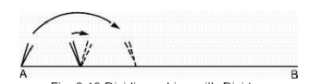
Fig. 2.19 Dividing a Line with Divider.
as pivot without making any permanent depression in the sheet. Repeat the process for
the number of parts required. Some difference will be there at the end after the first try.
Open or close the divider by an amount roughly equal to nth part of the difference
and make a second try. After second try, the difference at the end will be reduced and
about 3 to 4 tries will be sufficient to exactly divide the line into the required number
of equal parts. Now put marks on the sheet with the help of the divider in the form of
very small and just visible depressions by the needle; large holes in the sheet are not
desirable.
Using Triangle and a Scale: To divide a line AB into ‘n equal parts, draw a
construction line -From the point A at any suitable angle, as shown in Fig. 2.20. With
a scale or a divider, mark ‘n’ equal spaces each space being approximately equal to the
nth part. Join the last point marked, C, with point B and draw lines from all the marked
points parallel to BC. By intersection of these lines with the line AB, required equal parts are obtained.
Principle for this method is that when a line intersects at any angle to a series of
equally spaced parallel lines the intercepts are always equal. For line AC, we make the
intercepts equal and hence the parallel lines become equally spaced. Line AB now
intersects equally spaced parallel lines and the intercepts must become equal to each
other.
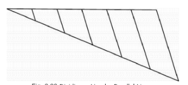
Fig. 2.20 Dividing a Line by Parallel Lines.
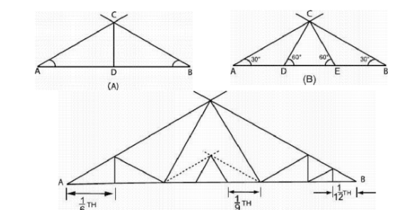
Using Angles Available on the Triangles: Basically there are two different
methods by which we can divide a given length of line into 2 or 3 equal parts and by
using a combination of these two methods, we can divide the line into 4, 6, 8, 9, 12
and 16, etc., parts.
Fig. 2.21 Dividing a Line Using Triangles.
In -first method, construction lines are drawn from the points A and of the given line
AB at equal angles. From the point of intersection, C, vertical construction line is then
dropped to divide the line AG into two equal parts, see Fig. 2.21 (A).
PROOF
<CAD = <CBD
<CDA = <CDG = 90°
CD is common.
Hence, triangles ACD and BCD are equal in measurements.
AD = GD
In the second method, construction lines are drawn from the points A and B of the
given line AB at 30° angle, see Fig. 2.21 (B). Two construction lines are now drawn with
the help of the 30°-60° triangle making an angle of 60° with the line AB on both sides
passing through the point C. points D and E are obtained dividing the le AG into three
equal parts.
PROOF
<CDE = 60°
<CDA = 120°
<ACD = 180° – 300 – 120°
= 30°
In triangle ACD, two angles are 30°, so their opposite sides should be equal. AD
= DC – – – – – (I)
<DCE = 180°- 60°- 60°
= 60°
Angles are equal in the triangle DCE, sides should also be equal.
DC = DE – – – – – (II)
From I and II:
AD = DE
Similarly:
DE = EB
Hence:
AD = DE = EB = 1/3 x AB
Combination of these two methods is shown in Fig. 2.21 (C).
Principle and Use of Decimal Diagonal Scale in Inch-Units PURPOSE
Decimal diagonal scale in inch units is used to measure inch-dimensions upto second
decimal places.
CONSTRUCTION
Diagonal scale consists of a top line graduated into inches. On the right side of the
zero, another inch is there divided into 10 equal parts each being 0.1-in long, see Fig-
There is a vertical line passing through the zero-mark divided into 10 equal
parts; horizontal lines are drawn from all of these points. On the lowermost or the 10th
horizontal line, the inch on the right side is again divided into 10 equal
parts. Points on the top line to the right of the zero are Joined diagonally with the
points on the lower line such that each point on the top line is joined with the one
space ahead point on the lower line.
PRINCIPLE
The name of the diagonal scale is taken from the fact that a diagonal line may divide a
small dimension further into any number of equal parts. Consider the triangle ABC
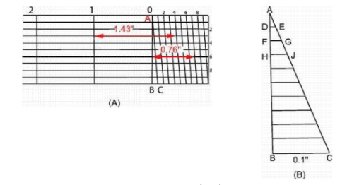
Fig. 2.22 Diagonal Scale
marked in Fig. 2.22 (A) and shown on enlarged scale Fig. 2.22 (B). BC is a dimension
equal to 0.1″ which is be further divided into 10 equal parts, AC being diagonal line.
<ABE = <ABC = 90°
<DAE <BAC (common)
The triangles DAE and BAC are similar and hence the ratio of their c0rrespondiflg
sides must also be equal.
DE AD
—
BC
= —
AB
1 div.
= ——–
10 div.
DE = 1/10 x BC
Similarly:
FG = 2/10 x BC
HJ = 3/10 x BC and so on
If BC = 0.1″, then DE = 0.01″, FG = 0.02″, HJ = 0.03 and so on
METHOD TO USE
To measure any dimension upto second decimal place, start from vertical line
corresponding to the whole inches left of the decimal, move towards the right, go
upto the zero, still move towards the right by number of divisions equal to the
number in the first decimal place come down on the diagonal line by number of
divisions to the number in the second decimal place and mark that point. Now
starting from the initial vertical line upto this marked point, the horizontal distance will
be the required dimension. Open the divider exactly equal to this dimension and transfer it to the drawing sheet.


